I was working on an Arduino Nano and I managed to get it to work twice, but the third time, the board refused to power up and since won't power up.
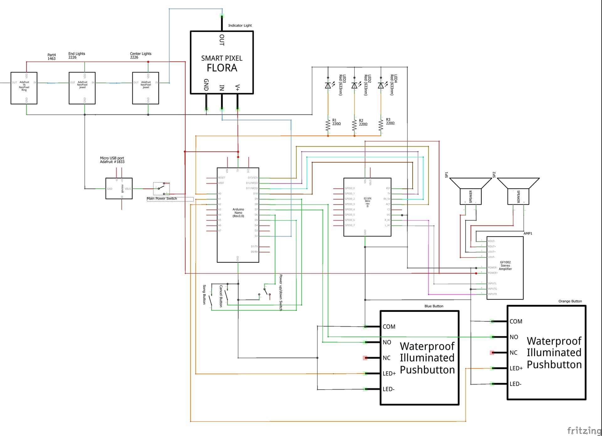
I am following this schematic,
I have removed it and tested it separately. No response from it. Even when plugged into computer.
I do have a DMM.
The issue is also that now also happening that when I plug in the power to the Micro USB port, the Audio board does not light up either anymore, so it might by the USB port so I will try to fix that.
I see 3 LEDs with 220Ω resistors (40mA total) connected to pin A0,
button LEDs with no current limit resistors connected to A1 and A2. How much current do those LEDs draw?.
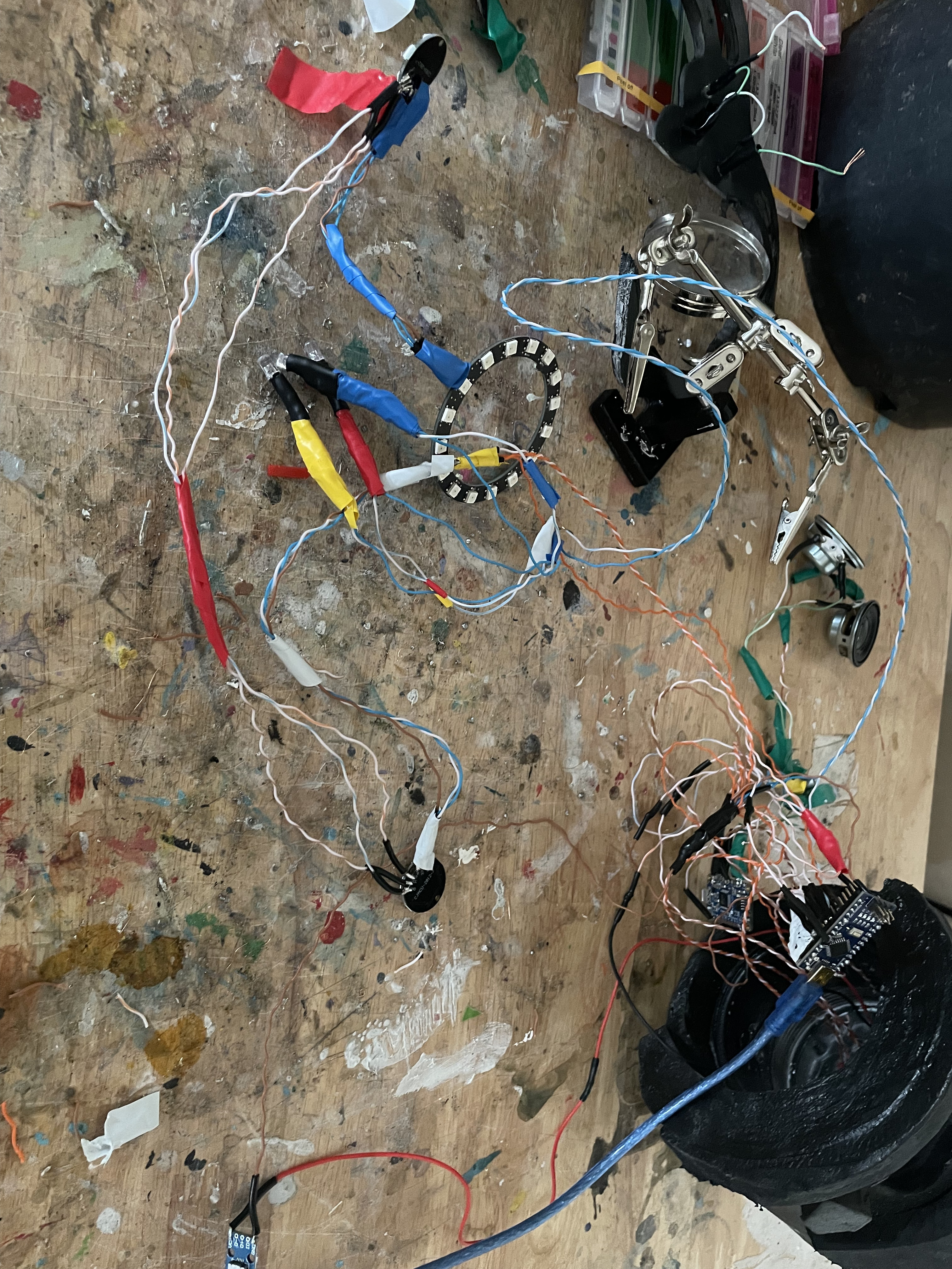
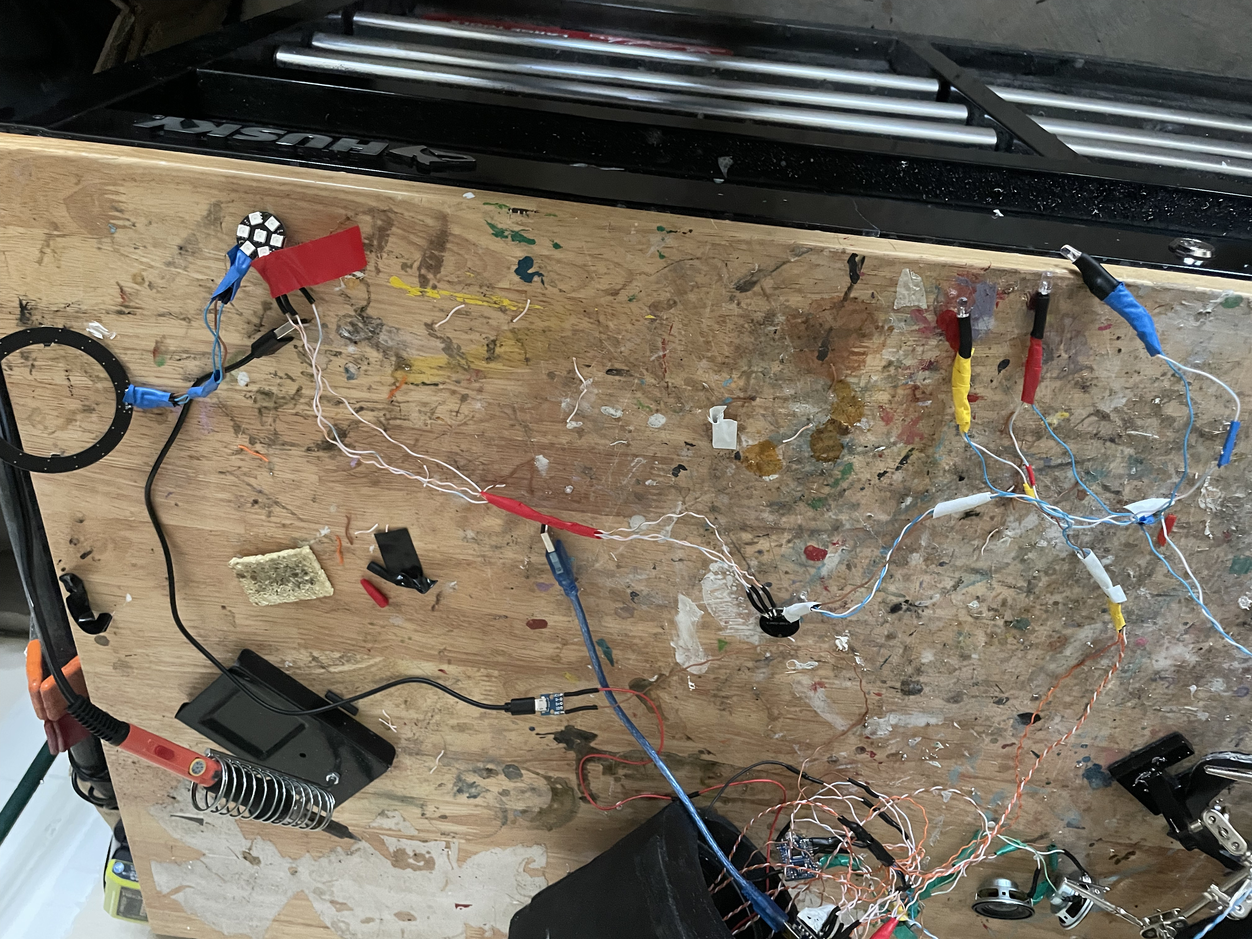
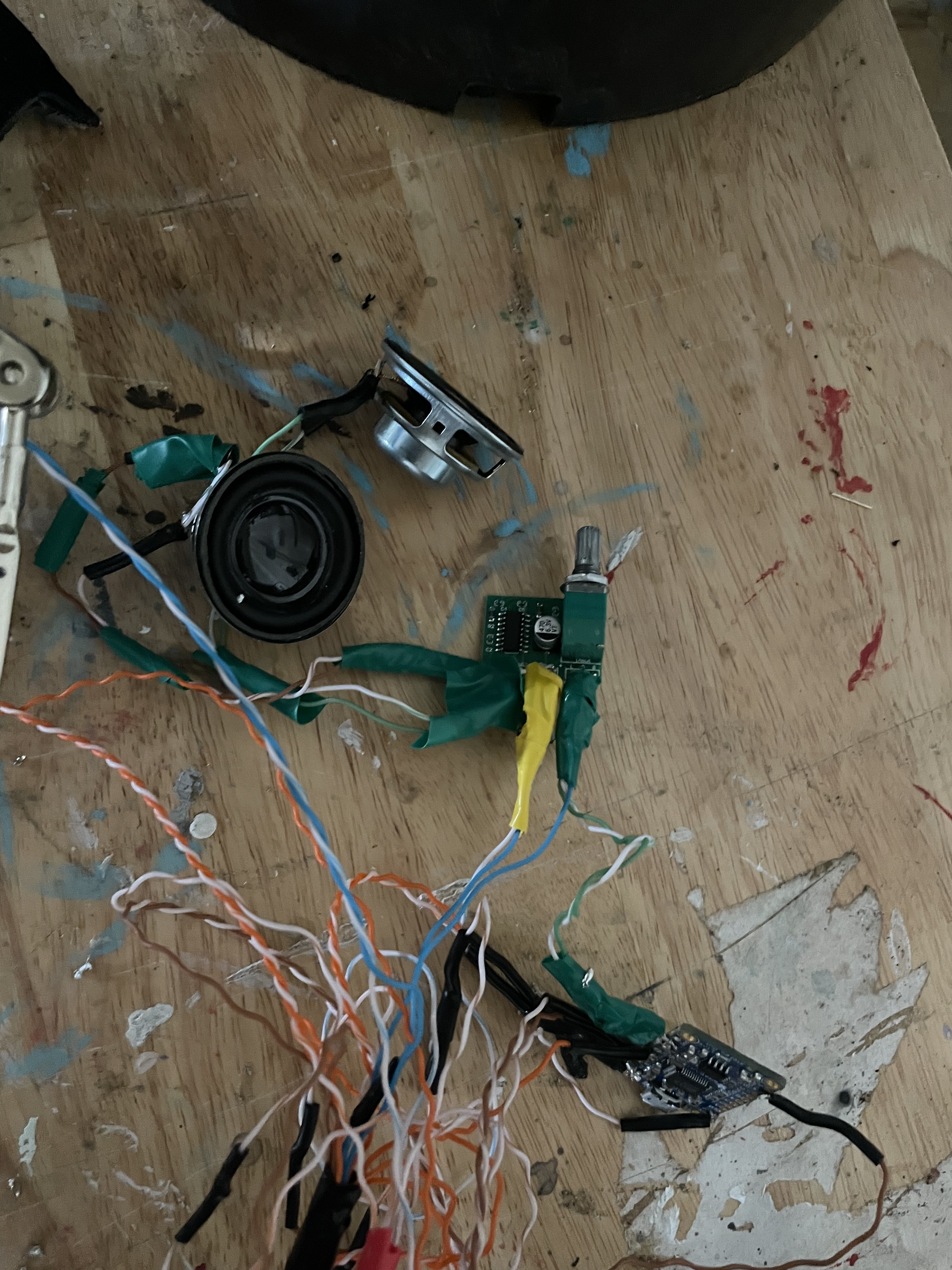
My work isn't pretty, but here it was before I removed the arduino. Everything follows the diagram above in the main question (except the usage of A1 and A2 since those are disabled) .
You have probably destroyed the back feed protection diode on the Nano. It conducts power from the USB port to the 5V board power and the 5V I/O pin.
If you look, you may even be able to see the damage visually, it may be burned. Because the diode can not conduct very much current, connecting current demanding loads to the 5V pin, is a recipe for disaster.
Do not use USB power that way. Power all your devices on 5V from a different supply or USB tap, and treat the 5V pin as a power input rather than a power output.
If you like "living on the edge", you can put a jumper short across the diode, now all the USB current can safely bypass the Nano. But then there is no input protection for your USB source, you can harm your PC's USB ports if you overload it that way. Also that removes the backfeed protection, when the PC is off and the Arduino is on, it can also harm the computer. The UNO has a resettable fuse to deal with that kind of problem, which the Nano lacks.
In a kind of perverse way, the diode is a fuse in these situations. It may have sacrificed a Nano to save your PC.
In fact, it would be a good test, to apply 5V to the 5V pin and see if the unit comes alive (with the USB unplugged).
According to the diagram I was using, it was used as an input for the power from the USB. The power in the diagram was wired to the 5V from the switch which the switch was connected to the USB. So I am likely misunderstanding what you are saying, but if I am understanding, it was wired that way.