Hi, I have been using a clone nano with MCP2515 board from amazon and got it to work. I have made several prototype projects getting the candata, and making stepper motors move for a gauge cluster project. I have had no noticeable issues, but I had 2 ESP8266 laying around and wanted to see if they would be faster (aside from buying ESP32 board or Teensy.. either way I have run into an issue. I cannot get CanHacker to connect to the board.
MCP -> ESP8266
VCC - VIN (powered by USB)
GND - GND
CS - D8
SO - D6
SI - D7
SCK - D5
INT - D4
With this wiring I can get a previous sketch that works on the Nano to work on the ESP8266.
#define DEBUG 1                             // turn On (1) or Off (0) debug & Serial.println

#if DEBUG == 1                              // if there is Serial.println, gauge operates slowly and quietly
#define debug(x) Serial.print(x)            // if there is NO Serial.println, gauge moves quickly and quietly to 1st position, but able to hear indicator movment afterwars
#define debugln(x) Serial.println(x)
#else
#define debug(x)
#define debugln(x)
#endif

int previous = 0;
const unsigned long eventInterval =  250;   // Set higher delay for each indicator step??  Maybe usefull if a unbaffled fuel tank is used and fuel float moves a lot
unsigned long previousTime = 0;

int ledState = LOW;                         // Blink without delay example, for blinking LED if sensor is unpluged or wire fault (open)


#include <SPI.h>
#include <mcp2515.h>

struct can_frame canMsg;
MCP2515 mcp2515(D8);                        // CS Pin

int Led = D3;                               // Led connected to D8 on Nano
byte val = 0;                               // Value to store canbus data from Brake Pedal data
byte oldval = 0;

int h1Mask  = 17;                           // Brake Pedal pressed = 0x11 (h10 is also high + h1) - testing function before using h2Mask only
int h2Mask  = 0x01;                         // Brake Pedal pressed = 0x01 or 00000001 Binary

void setup()
{
  Serial.begin(115200);
  SPI.begin();

  pinMode(Led, OUTPUT);                      // initialize digital pin Led as an output.
  digitalWrite(Led, LOW);

  mcp2515.reset();
  mcp2515.setBitrate(CAN_500KBPS, MCP_16MHZ);   // test between boards 8mhz and 16mhz!!!!!!!!!!!!!!!!!!!!!!!!!!!!!!!!!!!!!!!!!!!!!!!!!!!!!!!!
  mcp2515.setNormalMode();

  debugln("----------- CAN Read -----------");
  debugln("------ Brake Pedal Read ------");
  debugln("----------- LED Test -----------");
}

void loop()
{
  if  (mcp2515.readMessage(&canMsg) == MCP2515::ERROR_OK)
  {
    if ((canMsg.can_id == 0x0C9) && (canMsg.can_dlc == 8))

    {
      val = (canMsg.data[5]);                             // canMsg.data[ ] value now is val and is stored on line #29 or 30 depending one what is used later in code
    }
  }

  if (val < (oldval - 1) || val > (oldval + 1)) // add some deadband
  {
    oldval = val;                                // update value

    if (oldval != val) // only print if value changes
    {
      Serial.print("New Value is: ");
      Serial.println(val);
    }
    }

//      debug("Brake Pedal = ");                            // Print Brake Pedal =
//      debugln (canMsg.data[5]);                           // Prints value in Decimal


//Serial.println(val);

//Serial.println(oldval);

  unsigned long currentTime = millis();

  if (currentTime - previousTime >= eventInterval)        // If a delay is required, eventInverval value must be met betfore code runs
  {


         if (mcp2515.checkReceive() == 0)                      // 0 = disconected can bus - led will blink once on startup for some reason, maybe a capacitor will prevent it?
       {
         // since this statement runs as true for some reason at statup, added delay(100) in setup void and this to make it wait to turn on the led back off.
         // but the real true else case will run before the time here is true. if can is unplugged, LED operates as intended

         digitalWrite(Led, LOW);                             // to turn led back off after after startup
         if (millis() - previousTime >= 500)                 // value higher than "const unsigned long eventInterval =  250;" and it workeds as intended
         {
           digitalWrite (Led, HIGH);
         }
       }

       else                                                  // can conected
       {

         digitalWrite(Led, LOW);

    if (val & h2Mask)                                   // Pedal Pressed using h2mask to identify change in bit 1. 0 = LED off, 1 = Led on
    {
      ledState = HIGH;
      digitalWrite(Led, ledState);
    }
    else
    {
      ledState = LOW;
      digitalWrite(Led, ledState);
    }

    previousTime = currentTime;
  }
}
}
This sketch has an LED connected to it.
When it looses can bus, it turns LED ON.
If brake pedal is pressed, it turns on.
If can bus is connected and brake pedal is not pressed, its off.... code works. No change in wiring, only change in code is
MCP2515 mcp2515(D8); // CS Pin ESP8266
to
MCP2515 mcp2515(10); // CS Pin Nano
When I make the changes to canhacker sketch
// code from https://github.com/omarKmekkawy/Arduino_CANHacker

#include <can.h>
#include <mcp2515.h>

#include <CanHacker.h>
#include <CanHackerLineReader.h>
#include <lib.h>

#include <SPI.h>
#include <SoftwareSerial.h>

const int SPI_CS_PIN = D8;     //ESP8266
const int INT_PIN = D4;           //ESP8266

const int SS_RX_PIN = 3;
const int SS_TX_PIN = 4;

CanHackerLineReader *lineReader = NULL;
CanHacker *canHacker = NULL;

SoftwareSerial softwareSerial(SS_RX_PIN, SS_TX_PIN);

void handleError(const CanHacker::ERROR error);

void setup() {
    Serial.begin(115200);
    SPI.begin();
    softwareSerial.begin(115200);

    Stream *interfaceStream = &Serial;
    Stream *debugStream = &softwareSerial;


    canHacker = new CanHacker(interfaceStream, debugStream, SPI_CS_PIN);
    canHacker->setClock(MCP_16MHZ);
//    canHacker->enableLoopback(); // remove to disable loopback test mode
    lineReader = new CanHackerLineReader(canHacker);

    pinMode(INT_PIN, INPUT);
}

void loop() {
    CanHacker::ERROR error;

    if (digitalRead(INT_PIN) == LOW) {
        error = canHacker->processInterrupt();
        handleError(error);
    }

    // uncomment that lines for Leonardo, Pro Micro or Esplora
    // error = lineReader->process();
    // handleError(error);
}

// serialEvent handler not supported by Leonardo, Pro Micro and Esplora
void serialEvent() {
    CanHacker::ERROR error = lineReader->process();
    handleError(error);
}

void handleError(const CanHacker::ERROR error) {

    switch (error) {
        case CanHacker::ERROR_OK:
        case CanHacker::ERROR_UNKNOWN_COMMAND:
        case CanHacker::ERROR_NOT_CONNECTED:
        case CanHacker::ERROR_MCP2515_ERRIF:
        case CanHacker::ERROR_INVALID_COMMAND:
            return;

        default:
            break;
    }

    softwareSerial.print("Failure (code ");
    softwareSerial.print((int)error);
    softwareSerial.println(")");

    while (1) {
        delay(2000);
    } ;
}
It does not connect. I'm currently trying to search for softwareserial as pin 3 and 4 might need to be labeled differently.I think this is the issue maybe since the canbus "Brake Pedal Detection" sketch runs as expected.
I dont understand where pin 3 and pin 4 are for software serial as on the nano its not wired to any pin 3 or 4 and it works.. the nano is wired
MCP2515 nano wiring picture
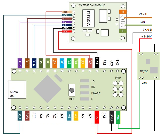
thank you,
Clint