Hey!
Im trying to activate a motor based on the acceleration data of the 6050 MPU .
Connected everything, wrote the code, plonked in a BD911 and a 330Ohm resistor. So far so good. I get 1A on the motor from a 9V Batterie when the PWM of the arduino is at 255 /4,5V and it draws around 12mA from the board. (Which should be fine, right?)
But as soon as the PWM deliveres that current (every current over 5mA) to the transistor while the "Adafruit_MPU6050.getEvent(&a, &g, &temp);" Gets called the arduino gets stuck. The TX light stops blinking for serial output and the PWM pin stays at the same level.
I call the function a few times in my code, it differs at what cycle the arduino gets stuck but its always exactly at that line.
Power cycling everything clears the issue.
Tried so far:
-Changing MPU device
-Giving MPU own Power source (needs common ground tho)
-SDA/SCL Pullup Resistors (tried with my calculated: 800Ohm to 3.3V and once the mentioned 4,7kOhm from the spreadsheet [Even tho they seem already populated onm the breakout board])
-Tried different PWM pins
-Code works when not calling the function while PWM pin is over 5mA / ~2,5V
-Not using any SerialWrite
i read a heated debate about some issues with FIFO storage and and the Wire library beeing broken but id doesnt seem to fit my problem/wasnt solved anyway.
If anyone has a idea that would be awesome. Thanks in advance!
Please post schematics for the build and datasheets for motor and driver and other special circuits.
Shakespeare type descriptions call for numerous of replies just to define the project and make things clear.
Helping You with real technical suggestion is the goal. Helping You to put the question together is annoying.
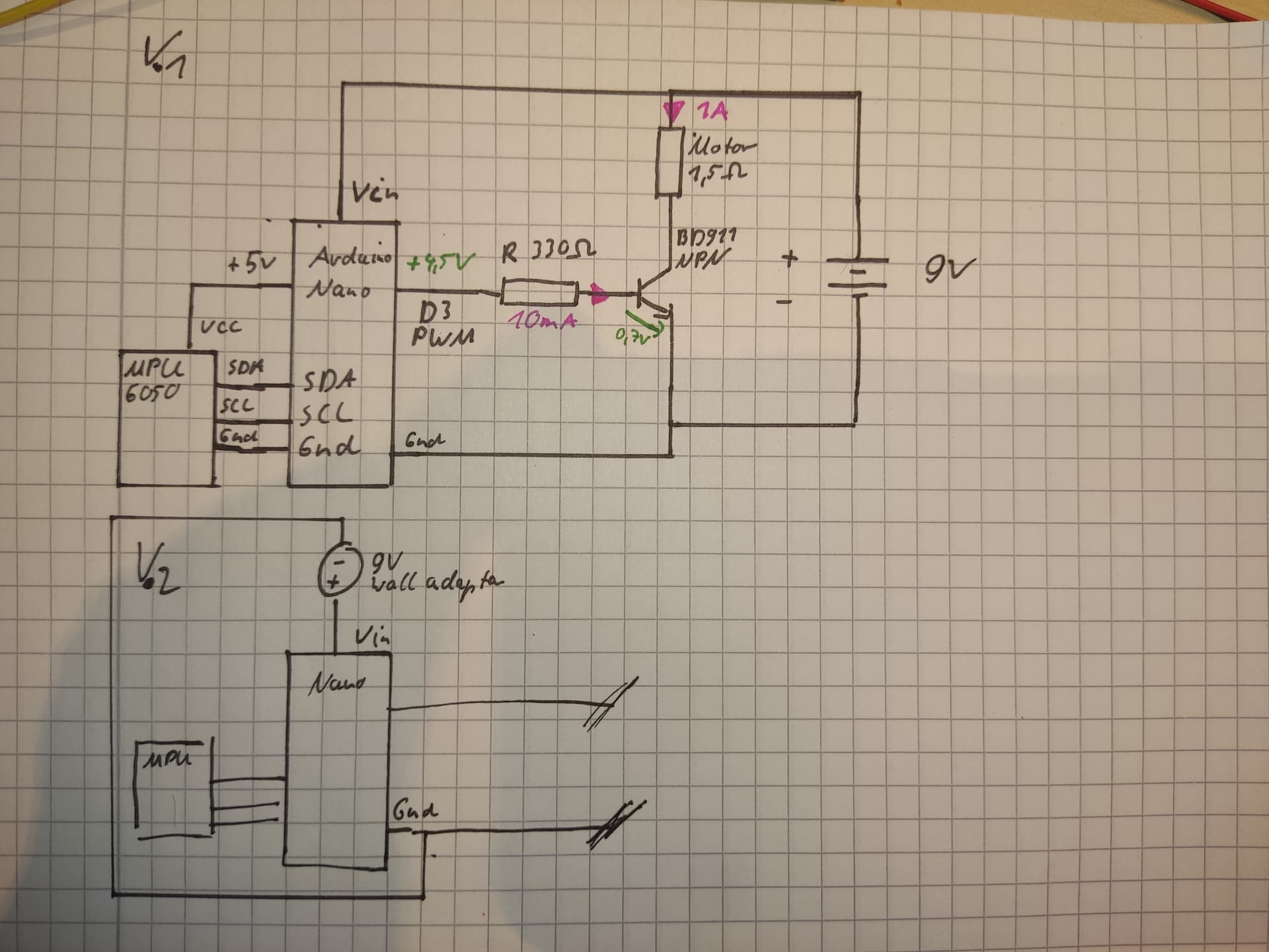
Schematic.
V.1 with only one 9v Battery as power source
V.2 With one Wall adapter 9v 15W and one 9V PP3 Battery. (Swtiched them too for testing)
I sadly do not have any documentation for the motor. Its an unbalanced mass motor with a 1,5Ohm winding resistance. Can measure the real resistance under load in a few days.
The IMU is a MPU 6050 GY-521.
The Arduino Nano is an ATmega328P with Old bootloader
The BD911
My Code:
#include <Adafruit_MPU6050.h>
#include <Adafruit_Sensor.h>
#include <Wire.h>
#define MPU6050_ADRESS 0x69
float gx = 0;
float gy = 0;
float gz = 0;
const int pwmtest = 10;
int level = 15;
Adafruit_MPU6050 mpu;

void setup(void)
{
    pinMode(pwmtest,OUTPUT);
    pinMode(LED_BUILTIN,OUTPUT);
    if (!mpu.begin()) {
        Serial.println("Failed to find MPU6050 chip");
        while (true) {}
    }
}

void loop()
{
    // normal readings
    mpu.enableSleep(false);
    mpu.enableCycle(false);
    sensorloop();
    analogWrite(pwmtest, 200);
    digitalWrite(LED_BUILTIN, HIGH);
    delay(2000);
}


void sensorloop()
{
    sensors_event_t a, g, temp;

    float xwrite;
    float ywrite;
    float zwrite;
    float xdmp = 0;
    float ydmp = 0;
    float zdmp = 0;
    for (byte i = 0; i < 30; i++) {

        for (byte j = 0; j < 5; j++) {
        mpu.getEvent(&a, &g, &temp); // The mentioned line where the Loop gets stuck when pwtest pin is at over 50/ ~5mA
        xdmp = a.acceleration.x+xdmp;
        ydmp = a.acceleration.y+ydmp;
        zdmp = a.acceleration.z+zdmp;
        delay(10);
        }

        xwrite = xdmp/5;
        ywrite = ydmp/5;
        zwrite = zdmp/5;

        if( i%2==0){
          for (byte k = 0; k < 1; k++) {
            gx = 0.9 * gx + 0.1*xwrite;
            gy = 0.9 * gy + 0.1*ywrite;
            gz = 0.9 * gz + 0.1*zwrite;
            }
        }
        float lx=xwrite-gx;
        float ly=ywrite-gy;
        float lz=zwrite-gz;
        float ala=sqrtf(lx*lx+ly*ly+lz*lz);
        xdmp = 0;
        ydmp = 0;
        zdmp = 0;

        int pwmala = ala*level;
          if(pwmala > 255){
            pwmala = 255;
          }
        delay(10);
    }

}
Short explaination: Setting "pwmtest" to 200 was for me to test at what point it got stuck. When i set the PWM pin to 30 right before the commented line everything workes just fine. Please dont try to figure out exactly what the rest of the code does. Its out of context but works. The variable "pwmtest" gets exchanged for "pwmala" in the real usecase.
i dont think there is any more information to give.
Thanks! Perfect!
Regarding ohms law 9 volt into a 1.5 ohm motor winding calls for 6 Amps! This is when starting the motor.
Is there any plate on the motor telling what the maximum voltage is?
My idea is to run the motor using a strong power supply and measure the current when running at the actual load. Then multiply that current by 5, preferably 10, to manage the inrush current when starting. It ought to be Voltage divided by 1.5 ohm.
One more suggestion. Make a temporary sketch just operating the motor. Try different PWMs. That way You will find out how to master the motor.
Do the same for the mpu, to be safe.