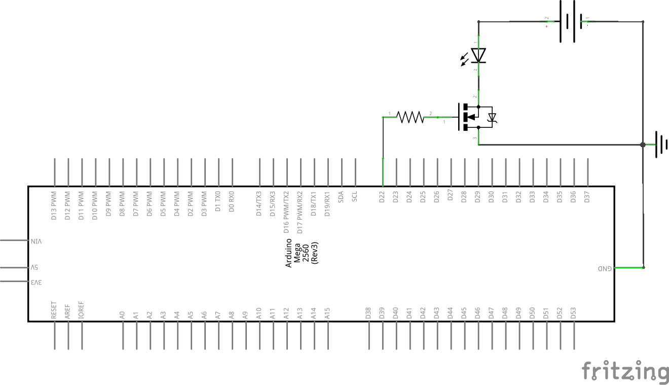
I'm trying to switch 12V LEDs using NChannel MOSFETs. I've got an arduino MEGA2560 to pull the gates high and low and in one configuration, where the LED is between the power supply and the MOSFET, the LED lights up when required.
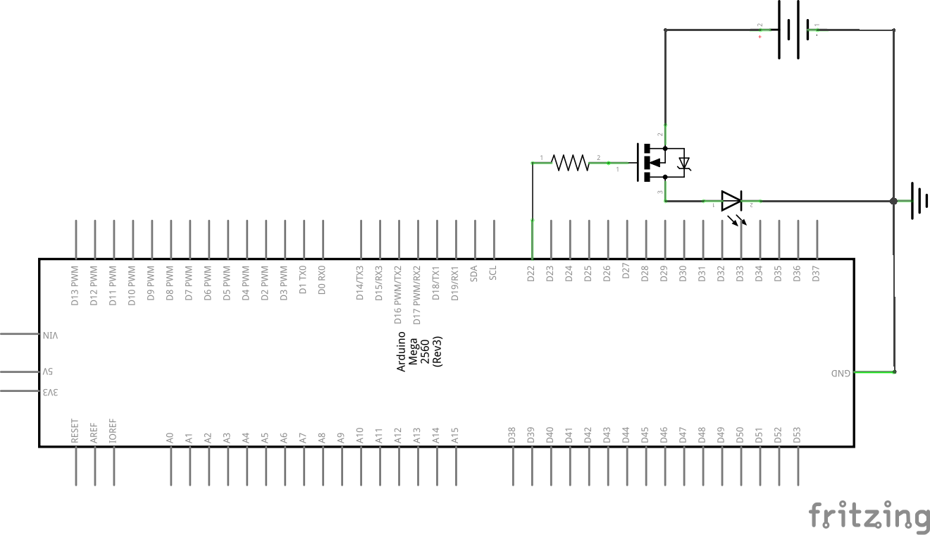
However when I move the LED to the other side of the MOSFET, ie between the MOSFET and ground, it doesn't
Can anyone enlighten me as to why the second configuration fails and what I can do to make it work?
The first schematic, you MUST have an resistor in series with the LED.
The second: The LED forward voltage + gate to source voltage are more than Vcc, no current can flow.
Replace the MOS transistor with an bipolar transistor ( and a resistor ) makes it work
With a switching circuit you always(*) have the load connected to the drain (or collector
if a BJT rather than MOSFET). Any attempt to put the load on the source side will
probably cook your MOSFET - for the device to be ON it must have the gate 5V higher
than the source, which cannot be done with your circuit.
(*) not strictly true - in fact there are chips to do this, called "high side MOSFET drivers" -
they require a bootstrap capacitor and diode and a PWM signal on the input to generate
a bootstrapped supply above the supply rail to allow the gate voltage to be above the
source and drain.
Your low side connection to Gnd would work, if:
You had the MOSFET connected correctly - you have it drawn upside down (Source & Drain reversed)
You had a Logic Level MOSFET, one with Vgs <=4.5V so the part is turned fully on with Arduino levels (Standard MOSFETs require 10V to turn full on)
You had a current limit resistor so total current is under 20mA (limit for most LEDs).
For a high side connection, the Gate must be go to 12V to turn a P-channel MOSFET off.
Arduino IO can't handle that, so a small NPN transistor is used to pull the Gate low to turn it in. Arduino drives base via 1K resistor, collector to Gate, emitter to Gnd.
Thanks for all the comments. I'd obviously misunderstood how mosfets work. I'll rework my designs, and I did draw the
mosfet upsidedown, I'll have to practise more with Fritzing
Fritzing diagrams have their place, which is to show how to
recreate a circuit with given components, but isn't really
intended to explain a circuit the way a circuit diagram (aka
schematic) does. A photo of a hand-drawn circuit diagram
is usually a lot easier to understand, and is quick and simple
to do