I finally found some time to start dabble with a esp32 i had on the shelf for
a while.
I have have been programming for years as a hobby and i have been curious about
embedded systems , now finally i got time.
So filled with ambition i ordered the sparkfun meter kit, rj11 plugs, etc
and started wiring this up. This is where my trouble starts.
I can get the anemometer working standalone, same with the rain gauge.
but when i connect the anemometer up with the wind vane, i dont get any readings.
Im guessing im wiring this up wrong and the diagrams on their site are to a beginner like me
worth close to nothing.
So what im asking for realy is some help with the wiring.
If there is anny information that is lacking in this cry for help please let me know and i will try to answer as good as i can
So to make make it a bit clearer for people to understand what the problem is will add a list of items in use and a image that discribes the problem( I hope )
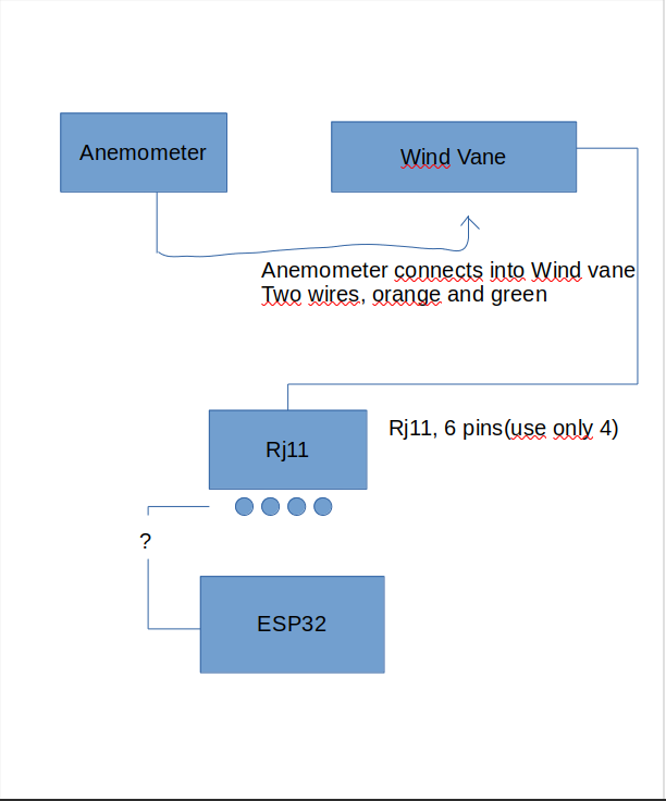
so the issue:
The anemometer and wind vane is connected together.
The anemometer connects to the wind vane via rj11, then the wind vane connects to
a rj11 socket. The rj11 socket needs to be wired to the esp32, This is where i come in trouble.
how do i wire this correctly to get independent reads from both peripherals
Posting code and schematics would be a good idea. Else You might receive more guesses then You have time to read.
Please look at the topic "How to get the best out of this forum".
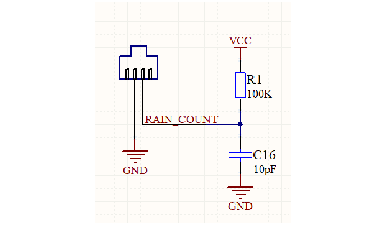
Connect the two innermost pins of the cable from the rain collector one to ground, the other to the rc circuit shown ( VCC = 3.3V ), connect the rain_count to pin 27 of esp ( so to match the basic example of sparkfun library )
Connect the two innermost pins of the cable from the wind sensor one to ground, the other to the rc circuit shown ( VCC = 3.3V ), the connections of the R/C is the wind_speed signal connect to pin 14 of esp
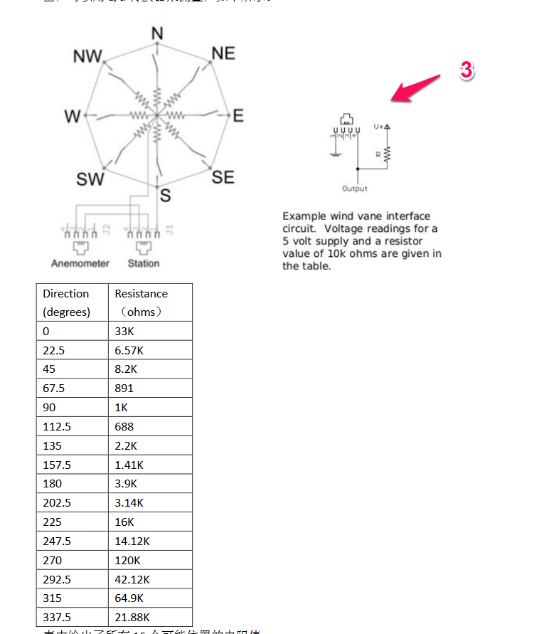
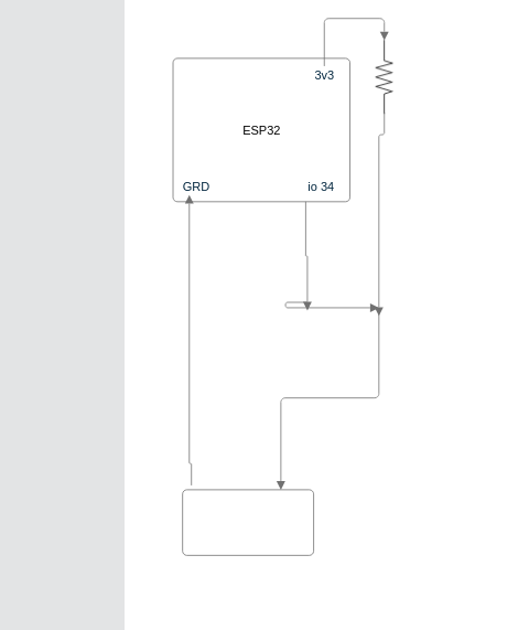
Connect the two outermost pins of the cable from the wind sensor one to ground, the other to the r circuit shown ( V+ = 3.3V ), connect the output to pin 35 of esp ( hope the sparkfun library consider a R = 10K )
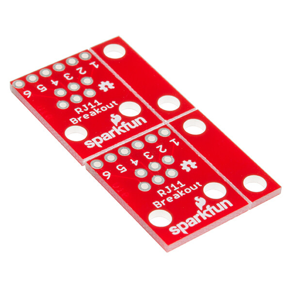
Ok, I spotted a problem. The breakout boards you linked to are for RJ45 sockets (8-pins), but your sockets are RJ11 (6-pins). So I doubt they will fit the sockets, and even if they do, this will confuse the wiring problems even further.
The next source of confusion may be that the RJ11 sockets have 6 pins but only 4 are used. But which 4? The images provided by Sparkfun are not helpful here because they show only 4 pins:
I have used these sensors before. Use your multimeter on resistance measurement range and try every possible pair of pins, while slowly rotating the anemometer and vane, to see how the resistance readings change. For most pairs, you will get no reading ("E" or "-" or something).
When you find the correct pair for the anemometer, you will see alternating readings of zero (or close to zero) and no reading ("E") as the anemometer rotates, 4 changes per rotation.
When you find the correct pair for the vane, you will get 16 different readings as the vane direction changes.
I do. But it may not be great example code for you because it is much more complex than you may need. This is because the code is optimised for low power consumption. Most of the complexity in the code is to achieve low power, not in reading the sensors.
In my project, an attiny85 chip is used to monitor the sensors and communicate the readings to an ESP8266 which transmits the readings to a server. I could not find a way to achieve low power with the ESP chip alone, so I added the ATtiny. This makes the project much more complex and I would not recommend following this design. If I were to re-build the project, I would try again to achieve low power in a different way.
Actually i'm using ESP32 and couple of sensors to form a low cost solar powered weather station. But i didn't have any problem with the power i guess till now. Thank you.