i am trying to take 3 spark outputs from a megasquirt V2.2 and run them into 3 uno inputs.
then have the uno output to the 3 spark IGBT's
so far it almost works but the sparkC does not always come through. not sure if the code is not correct or if the megasquirt is not outputting.
i put in the delay to shorten up the serial monitor info
right now only the input is wired up.
i have one jumper from uno ground to chassis ground of the megasquirt
int sparkA = 2;
int sparkB = 4;
int sparkC = 7;
int copA = 3;
int copB = 5;
int copC = 6;

void setup() {
 Serial.begin(9600);
 pinMode(2,    INPUT);       //spark outputs
 pinMode(4,    INPUT);
 pinMode(7,    INPUT);
 pinMode(copA, OUTPUT);      //coil outputs
 pinMode(copB, OUTPUT);
 pinMode(copC, OUTPUT);
}

void loop() {
   while  (digitalRead(sparkA) == HIGH)
   {
    digitalWrite(copA, HIGH);
    Serial.println("  A!");
    delay(1);
   }

   while  (digitalRead(sparkB) == HIGH)
   {
    digitalWrite(copB, HIGH);
    Serial.println("  BBBBBBBB");
    delay(1);
   }

   while  (digitalRead(sparkC) == HIGH)
   {
    digitalWrite(copC, HIGH);
    Serial.println("  CCCCCCCCCCCCCCCCCCCCC");
    delay(1);
   }
    }
and the serial monitor shows..........
  A!
  A!
  A!
  A!
  BBBBBBBB
  BBBBBBBB
  BBBBBBBB
  BBBBBBBB
  CCCCCCCCCCCCCCCCCCCCC
  CCCCCCCCCCCCCCCCCCCCC
  CCCCCCCCCCCCCCCCCCCCC
  A!
  A!
  A!
  A!
  BBBBBBBB
  BBBBBBBB
  BBBBBBBB
  BBBBBBBB
  CCCCCCCCCCCCCCCCCCCCC
  CCCCCCCCCCCCCCCCCCCCC
  CCCCCCCCCCCCCCCCCCCCC
  A!
  A!
  A!
  A!
  BBBBBBBB
  BBBBBBBB
  BBBBBBBB
  BBBBBBBB
  CCCCCCCCCCCCCCCCCCCCC
  CCCCCCCCCCCCCCCCCCCCC
  CCCCCCCCCCCCCCCCCCCCC
  A!
  A!
  A!
  A!
  A!
  A!
  A!
  A!
  BBBBBBBB
  BBBBBBBB
  BBBBBBBB
  BBBBBBBB
  A!
  A!
  A!
  A!
  A!
  A!
  A!
  A!
  BBBBBBBB
  BBBBBBBB
  BBBBBBBB
  A!
  A!
  A!
  A!
  A!
  A!
  A!
  A!
  BBBBBBBB
  BBBBBBBB
  BBBBBBBB
  BBBBBBBB
  A!
  A!
  A!
  A!
  A!
  A!
  A!
  A!
  BBBBBBBB
  BBBBBBBB
  BBBBBBBB
  BBBBBBBB
  A!
  A!
  A!
  A!
  A!
  A!
  A!
  A!
  BBBBBBBB
  BBBBBBBB
  BBBBBBBB
  BBBBBBBB
  A!
  A!
  A!
  A!
  A!
  A!
  A!
  A!
  BBBBBBBB
  BBBBBBBB
  BBBBBBBB
  BBBBBBBB
  A!
  A!
  A!
  A!
  A!
  A!
  A!
  A!
  BBBBBBBB
  BBBBBBBB
  BBBBBBBB
  BBBBBBBB
  A!
  A!
  A!
  A!
  A!
  A!
holy cow got it working perfect at idle!
however it stumbles like a rev limiter with any throttle and the IGBT get hot fast when trying.
something is dwelling the IGBT's too much?
how would i include a fixed dwell value for the digitalWrite(copX, HIGH); ?
i only need about 1-2 millis per (digitalRead(sparkX) == HIGH).
the megasquirt is supposed to output a dwell amount that is set it its software but i have my doubts of it being correct for this
int sparkA = 2;
int sparkB = 4;
int sparkC = 7;
int copA = 3;
int copB = 5;
int copC = 6;

void setup() {
 Serial.begin(9600);
 pinMode(2,    INPUT);       //spark signals
 pinMode(4,    INPUT);
 pinMode(7,    INPUT);
 pinMode(copA, OUTPUT);      //coil outputs
 pinMode(copB, OUTPUT);
 pinMode(copC, OUTPUT);
}

void loop() {
        if  (digitalRead(sparkA) == HIGH)
   {
    digitalWrite(copA, HIGH);
    Serial.println("  A");
    delay(1);
   }

   else if  (digitalRead(sparkB) == HIGH)
   {
    digitalWrite(copB, HIGH);
    Serial.println("  BBBBBBBB");
    delay(1);
   }
   else if  (digitalRead(sparkC) == HIGH)
   {
    digitalWrite(copC, HIGH);
    Serial.println("  CCCCCCCCCCCCCCCCCCCCC");
    delay(1);
   }
   else {
    digitalWrite(copA, LOW);
    digitalWrite(copB, LOW);
    digitalWrite(copC, LOW);
   }
    }
If something gets hot, the circuit diagram should be checked first. Do it yourself, or post it here.
Inputs usually should be enabled with pinMode(pin, INPUT_PULLUP), with HIGH being the default and unconnected value.
the IGBT run cool at idle for minutes on end
only when i apply some throttle does the IGBT get hot.
i will adjust the pinMode(pin, INPUT_PULLUP) tomorrow
Give this a shot (compiles, not tested; monitor temps closely...)
//ref: sketch_oct24b

#define NUM_CYLINDERS       3           //# of cylinders
#define DWELL_TIME          1000ul      //microseconds of dwell time

//pin definitions
const byte sparkA = 2;
const byte sparkB = 4;
const byte sparkC = 7;
const byte copA = 3;
const byte copB = 5;
const byte copC = 6;

//spark control structure
typedef struct structSpkCtl
    {
        byte            pinSpkIn;       //pin number for trigger input
        byte            lastPinSpk;     //used for state change detect logic
        byte            pinCOPOut;      //pin number for COP
        bool            bState;         //COP on (true) or off (false)
        unsigned long   ulDwell;        //in theory allows cylinder specific dwell
        unsigned long   ulTOn;

    };

//spark control


structSpkCtl SpkCtl[NUM_CYLINDERS] =
    {
        {
            .pinSpkIn = sparkA,
            .lastPinSpk = LOW,
            .pinCOPOut = copA,
            .bState = false,
            .ulDwell = DWELL_TIME,
            .ulTOn = 0

        },
        {
            .pinSpkIn = sparkB,
            .lastPinSpk = LOW,
            .pinCOPOut = copB,
            .bState = false,
            .ulDwell = DWELL_TIME,
            .ulTOn = 0
        },
        {
            .pinSpkIn = sparkC,
            .lastPinSpk = LOW,
            .pinCOPOut = copC,
            .bState = false,
            .ulDwell = DWELL_TIME,
            .ulTOn = 0

        }
    };


void setup()
{
    Serial.begin(9600);

    //setup pins and initialize "last" reading of trigger inputs
    for( int i=0; i<NUM_CYLINDERS; i++ )
    {
        pinMode( SpkCtl[i].pinSpkIn, INPUT );
        pinMode( SpkCtl[i].pinCOPOut, OUTPUT );
        //
        SpkCtl[i].lastPinSpk = digitalRead( SpkCtl[i].pinSpkIn );

    }//for

}//setup

void loop()
{
    ReadSparkInputs();      //go read a cylinder
    CheckCOPOutputs();      //see if a cylinder's dwell time has ended

}//loop

void ReadSparkInputs( void )
{
    byte
        spkState;
    static byte
        idxCylinder = 0;

    //if COP is now on for this cylinder, skip checking trigger
    if( SpkCtl[idxCylinder].bState == false )
    {
        //read trigger input
        spkState = digitalRead( SpkCtl[idxCylinder].pinSpkIn );
        //is pin reading now different from last read?
        if( spkState != SpkCtl[idxCylinder].lastPinSpk )
        {
            //yes...make now-reading "last" reading
            SpkCtl[idxCylinder].lastPinSpk = spkState;
            //if trigger input has gone high...
            if( spkState == HIGH )
            {
                //turn on the COP for that cylinder
                digitalWrite( SpkCtl[idxCylinder].pinCOPOut, HIGH );
                //log the time of turn-on
                SpkCtl[idxCylinder].ulTOn = micros();
                //and set on-flag to true
                SpkCtl[idxCylinder].bState = true;

            }//if

        }//if

    }//if

    //check one cylinder each pass
    idxCylinder++;
    if( idxCylinder == NUM_CYLINDERS )
        idxCylinder = 0;

}//ReadSparkInputs

void CheckCOPOutputs( void )
{
    static byte
        idxCylinder = 0;

    //is COP for this cylinder currently on?
    if( SpkCtl[idxCylinder].bState )
    {
        //yes...has dwell time expired?
        if( (micros() - SpkCtl[idxCylinder].ulTOn) >= SpkCtl[idxCylinder].ulDwell )
        {
            //yes; set COP output low
            digitalWrite( SpkCtl[idxCylinder].pinCOPOut, LOW );
            //and clear on-flag
            SpkCtl[idxCylinder].bState = false;

        }//if

    }//if

    //check one COP's dwell time per pass
    idxCylinder++;
    if( idxCylinder == NUM_CYLINDERS )
        idxCylinder = 0;

}//CheckCOPOutputs
Hi,
Can you please post a copy of your circuit, in CAD or a picture of a hand drawn circuit in jpg, png?
Have you got a scope to check the waveforms you are reading at input and sending out the outputs?
Thanks.. Tom.. 
coming out of the megasquirt on 3 actual wires not 6
sparkA = 2;
sparkB = 4;
sparkC = 7;
then 3 wires coming out of the uno that are Y to the 330 resistors
so a 330 per ecospark
copA = 3;
copB = 5;
copC = 6;
leg #2 of the IGBT's is the ground of the 2 wire coil on plug
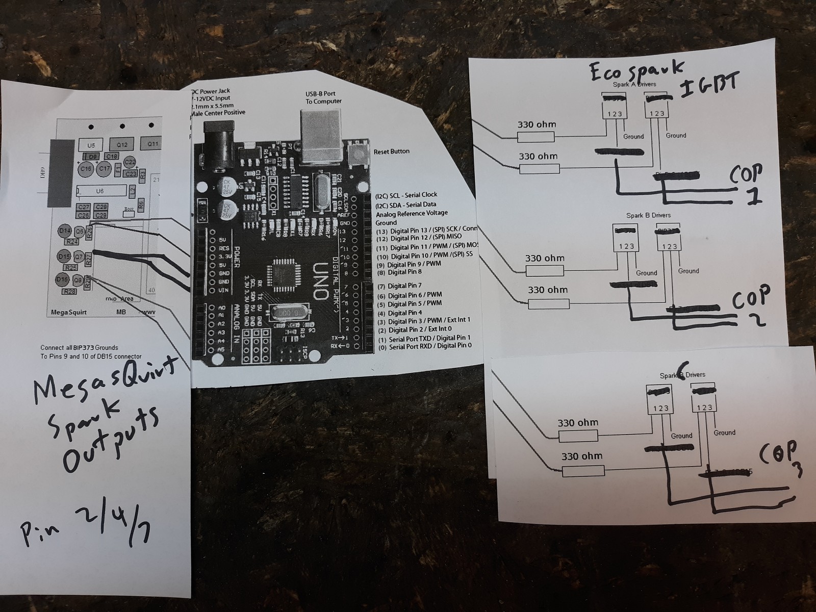
coming out of the megasquirt
Can you see the details on that image because I can't
sorry had a moment trying to use microsoft tools and failed
can you see my literal print/cut/paste image?
i got one of these to monitor
the current to the cop's
huge thanks to blackfin!
the code seems to be working great and IGBT are cool at all rpm so far
need to bundle this up and go for a drive.
in this area what are the . periods doing????
structSpkCtl SpkCtl[NUM_CYLINDERS] =
{
{
.pinSpkIn = sparkA,
.lastPinSpk = LOW,
.pinCOPOut = copA,
.bState = false,
.ulDwell = DWELL_TIME,
.ulTOn = 0
},
{
.pinSpkIn = sparkB,
.lastPinSpk = LOW,
.pinCOPOut = copB,
.bState = false,
.ulDwell = DWELL_TIME,
.ulTOn = 0
},
{
.pinSpkIn = sparkC,
.lastPinSpk = LOW,
.pinCOPOut = copC,
.bState = false,
.ulDwell = DWELL_TIME,
.ulTOn = 0
}
};
in this area what are the . periods doing
Telling the compiler where to put stuff.
Please remember to use code tags when posting code
turbothis:
huge thanks to blackfin!
the code seems to be working great and IGBT are cool at all rpm so far
need to bundle this up and go for a drive.
in this area what are the . periods doing????
structSpkCtl SpkCtl[NUM_CYLINDERS] =
{
{
.pinSpkIn = sparkA, ...
As AWOL noted, it's the syntax required for initializing the elements of a structure (or, in this case, an array of structures.)
Good luck on your drive. Be careful...
TheMemberFormerlyKnownAsAWOL:
Please remember to use code tags when posting code
would be nice to have the quick reply to have the tags too
thanks for the help
i drove around and it did great
i only got some stumbles at idle in gear at a stop light.
not sure what that is from yet
is there an easy arduino example of this array of structure thing?
might also have an injector going bad.......
turbothis:
would be nice to have the quick reply to have the tags too
thanks for the help
i drove around and it did great
i only got some stumbles at idle in gear at a stop light.
not sure what that is from yet
Keep in mind that the plug fires on the trailing edge of the COP drive:
digitalWrite( SpkCtl[idxCylinder].pinCOPOut, LOW );
How is your static timing set? Does the MS perform any spark advance/retard?
Does the trigger signal (e.g. sparkA) take the dwell you're injecting here into account?
Because the spark fires after the dwell period and the dwell period is 1mS right now, that means that at idle the spark occurs ~6-degrees after the trigger; at 7000RPM 1mS to dwell means 42-degrees of crank rotation. In both cases, the result is that the spark event is retarded relative to the trigger.
Unless the static dwell is accounted for in the trigger, the spark timing may be late.
Dwell really should be dynamic; you may not need as much dwell at low manifold vacuum as at WOT when cylinder pressures are higher. Same for coolant and manifold air temperature; colder == higher dwell...
turbothis:
would be nice to have the quick reply to have the tags too
You can turn on the full editor functionality for Quick Reply with a setting in your profile or, of course, you can just type in the tags
MS does the full timing curve
the trigger signal does have dwell on the output. i can set this to zero in the software though. or small....
i was hoping to have the dwell input pass right through the UNO.
so when the MS outputs and dwells this would be the task done by the UNO
turbothis:
MS does the full timing curve
the trigger signal does have dwell on the output. i can set this to zero in the software though. or small....
i was hoping to have the dwell input pass right through the UNO.
so when the MS outputs and dwells this would be the task done by the UNO
The code that I did looks for a rising edge on the trigger (sparkX) input and triggers a high level on the COP output for 1mS.
Would you rather the Uno simply drive its output to be a copy of the input trigger signal? I'm a little confused: why not drive the COPs directly with the MS if you want to have the dwell "dwell input pass right through the UNO"? What is the Uno actually doing?
sorry for the confusion!
the main goal is to drive the COP's with the uno as it function much better at this than the MS. the MS will have massive resets on cranking and while driving when it has the IGBT wired to it.
"Would you rather the Uno simply drive its output to be a copy of the input trigger signal?"
pretty much
If you want the Uno to follow the MS perhaps try this:
//ref: sketch_oct25a

//pin definitions
#define TRGA_MASK   0b00000100  //PD2
#define TRGB_MASK   0b00010000  //PD4
#define TRGC_MASK   0b10000000  //PD7

#define COPA_MASK   0b00001000  //PD3
#define COPB_MASK   0b00100000  //PD5
#define COPC_MASK   0b01000000  //PD6


void setup()
{
    Serial.begin(9600);

    //set triggers as inputs (0), COPs as outputs (1)
    DDRD &= ~(TRGA_MASK | TRGB_MASK | TRGC_MASK);
    DDRD |= (COPA_MASK | COPB_MASK | COPC_MASK);

}//setup

void loop()
{
    byte
        prt,
        msk;

    //read the port pins
    prt = PIND;
    //COPA follows trigger A
    msk = (prt & TRGA_MASK) ? COPA_MASK:0;
    //COPB follows trigger B
    msk |= (prt & TRGB_MASK) ? COPB_MASK:0;
    //COPC follows trigger C
    msk |= (prt & TRGC_MASK) ? COPC_MASK:0;

    //mask out bits 0 and 1 for OR
    msk &= 0xfc;

    //write COPs
    //preserve bits 0 and 1 and OR in msk
    PORTD = (PORTD & 0b00000011) | msk;

}//loop
(Note: This could be made simpler if you swapped the function of pins 6 and 7; the logic then becomes a simple shift...)
