Need help with Seeduino XIAO + TF-Luna Lidar

Hi all,

I have a Seeeduino XIAO. It speaks 3.3V TTL, as does the TF-Luna, so no TTL coverter is required, which is nice.

I have installed Bud Reyerson's TFMini Plus library, and am attempting to run his example code. I am using UART communications, with software serial on ports 9 and 10.

Here is my code. It is exactly the example, except I put in my pins 9 and 10.

/* File Name: TFMP_example.ino
 * Developer: Bud Ryerson
 * Inception: 29JAN2019
 * Last work: 10SEP2021

 * Description: Arduino sketch to test the Benewake TFMini Plus
 * time-of-flight Lidar ranging sensor using the TFMPlus Library.

 * Default settings for the TFMini Plus are a 115200 serial baud rate
 * and a 100Hz measurement frame rate. The device will begin returning
 * measurement data right away:
 *   Distance in centimeters,
 *   Signal strength in arbitrary units,
 *   and an encoded number for Temperature in degrees centigrade.

 * Use the 'sendCommand()' to send commands and return a status code.
 * Commands are selected from the library's list of defined commands.
 * Parameters can be entered directly (115200, 250, etc) but for
 * safety, they should be chosen from the library's defined lists.
 */

#include <TFMPlus.h>  // Include TFMini Plus Library v1.5.0
TFMPlus tfmP;         // Create a TFMini Plus object

#include "printf.h"   // Modified to support Intel based Arduino
                      // devices such as the Galileo. Download from:
                      // https://github.com/spaniakos/AES/blob/master/printf.h

// The Software Serial library is an alternative for devices that
// have only one hardware serial port. Delete the comment slashes
// on lines 37 and 38 to invoke the library, and be sure to choose
// the correct RX and TX pins: pins 10 and 11 in this example. Then
// in the 'setup' section, change the name of the hardware 'Serial2'
// port to match the name of your software serial port, such as:
// 'mySerial.begin(115200); etc.

#include <SoftwareSerial.h>       
SoftwareSerial mySerial( 9, 10);   
                                    
void setup()
{
    Serial.begin( 115200);   // Intialize terminal serial port
    delay(20);               // Give port time to initalize
    printf_begin();          // Initialize printf.
    printf("\r\nTFMPlus Library Example - 10SEP2021\r\n");  // say 'hello'

    mySerial.begin( 115200);  // Initialize TFMPLus device serial port.
    delay(20);               // Give port time to initalize
    tfmP.begin( &mySerial);   // Initialize device library object and...
                             // pass device serial port to the object.

    // Send some example commands to the TFMini-Plus
    // - - Perform a system reset - - - - - - - - - - -
    printf( "Soft reset: ");
    if( tfmP.sendCommand( SOFT_RESET, 0))
    {
        printf( "passed.\r\n");
    }
    else tfmP.printReply();
  
    delay(500);  // added to allow the System Rest enough time to complete

  // - - Display the firmware version - - - - - - - - -
    printf( "Firmware version: ");
    if( tfmP.sendCommand( GET_FIRMWARE_VERSION, 0))
    {
        printf( "%1u.", tfmP.version[ 0]); // print three single numbers
        printf( "%1u.", tfmP.version[ 1]); // each separated by a dot
        printf( "%1u\r\n", tfmP.version[ 2]);
    }
    else tfmP.printReply();
    // - - Set the data frame-rate to 20Hz - - - - - - - -
    printf( "Data-Frame rate: ");
    if( tfmP.sendCommand( SET_FRAME_RATE, FRAME_20))
    {
        printf( "%2uHz.\r\n", FRAME_20);
    }
    else tfmP.printReply();
    // - - - - - - - - - - - - - - - - - - - - - - - -

/*  // - - - - - - - - - - - - - - - - - - - - - - - -  
    // The next two commands may be used to switch the device 
    // into I2C mode.  This sketch will no longer receive UART
    // (serial) data.  The 'TFMPI2C_example' sketch in the 
    // TFMPI2C Library can be used to switch the device back
    // to UART mode.
    // Don't forget to switch the cables, too.
    // - - - - - - - - - - - - - - - - - - - - - - - -
    printf( "Set I2C Mode: ");
    if( tfmP.sendCommand( SET_I2C_MODE, 0))
    {
        printf( "mode set.\r\n");
    }
    else tfmP.printReply();
    printf( "Save settings: ");
    if( tfmP.sendCommand( SAVE_SETTINGS, 0))
    {
        printf( "saved.\r\n");
    }
    else tfmP.printReply();
    // - - - - - - - - - - - - - - - - - - - - - - - -    
*/

  delay(500);            // And wait for half a second.
}

// Initialize variables
int16_t tfDist = 0;    // Distance to object in centimeters
int16_t tfFlux = 0;    // Strength or quality of return signal
int16_t tfTemp = 0;    // Internal temperature of Lidar sensor chip

// Use the 'getData' function to pass back device data.
void loop()
{
    delay(50);   // Loop delay to match the 20Hz data frame rate

    if( tfmP.getData( tfDist, tfFlux, tfTemp)) // Get data from the device.
    {
      printf( "Dist:%04icm ", tfDist);   // display distance,
      printf( "Flux:%05i ",   tfFlux);   // display signal strength/quality,
      printf( "Temp:%2i%s",  tfTemp, "C");   // display temperature,
      printf( "\r\n");                   // end-of-line.
    }
    else                  // If the command fails...
    {
      tfmP.printFrame();  // display the error and HEX dataa
    }
}

Here is my device:

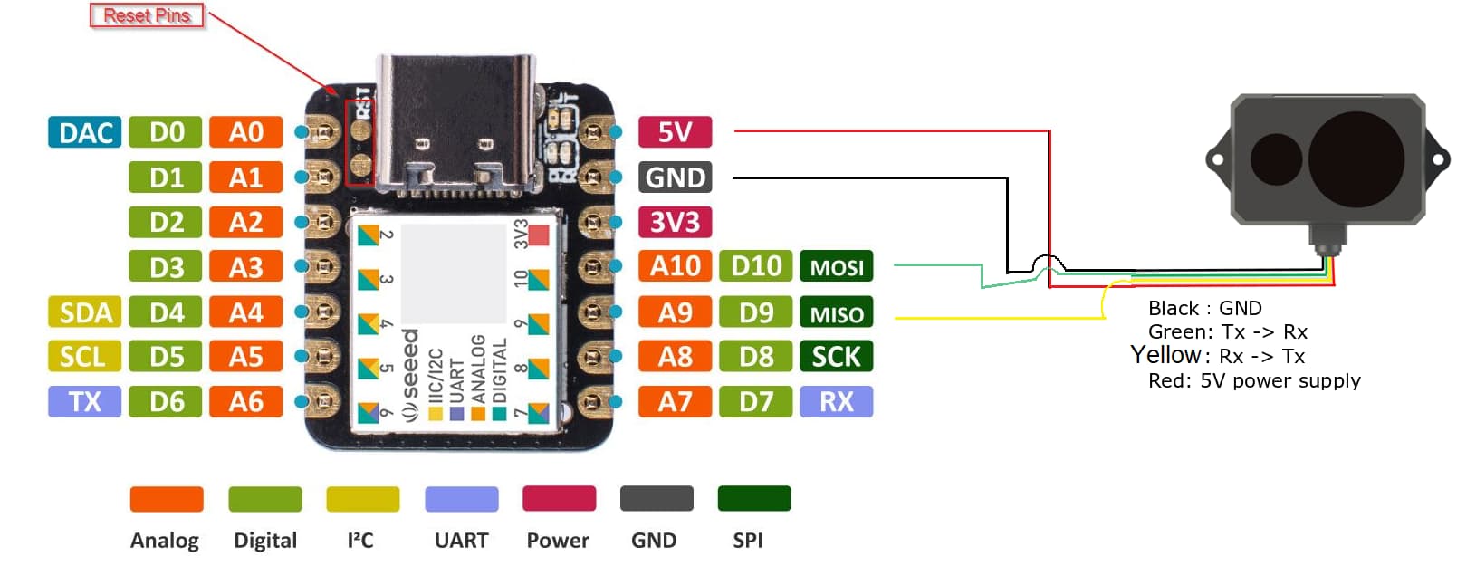
Here is the pinout of the Seeeduino XIAO:

Here is the pinout of the TF-Luna:

When I run the code, this is the output:

20:12:21.532 -> Status: HEADER
20:12:21.532 -> Data: 59 AD 93 80 AE 86 6A A1 FE
20:12:22.557 -> Status: HEADER
20:12:22.557 -> Data: 59 AD 93 80 AF 86 6B 42 FE
20:12:23.614 -> Status: HEADER
20:12:23.614 -> Data: FE 59 AD 93 80 C5 50 25 E1
20:12:24.666 -> Status: HEADER
20:12:24.666 -> Data: B1 86 6B A1 FF 59 AD 93 80
20:12:25.721 -> Status: HEADER
20:12:25.721 -> Data: FF 59 AD 93 80 58 23 2D E4
20:12:26.763 -> Status: HEADER
20:12:26.763 -> Data: EA 59 AD 93 80 B1 86 6B A1

I tried switching pins 9 and 10 in the code and then I get:
20:38:19.311 -> Status: HEADER
20:38:19.311 -> Data: 00 00 00 00 00 00 00 00 00
20:38:20.388 -> Status: HEADER
20:38:20.388 -> Data: 00 00 00 00 00 00 00 00 00
20:38:21.412 -> Status: HEADER
20:38:21.412 -> Data: 00 00 00 00 00 00 00 00 00
20:38:22.479 -> Status: HEADER
20:38:22.479 -> Data: 00 00 00 00 00 00 00 00 00

Can anyone help me talk to the TF-Luna?

Thanks.

From the dangling, unconnected wires (which, incidentally, is never a good idea!) it appears that you did not apply 3.3V to the configuration input on pin 5, as required to enable UART output.

Are you intending to use I2C or UART for data? Please post a hand drawn wiring diagram, showing which pins are connected, with labels.

Here is what I have wired up right now. The device has blue wires for the TX and RX lines. I have used Green and Yellow in the schematic.

I have been looking at YouTube videos and they left the last 2 pins hanging free so I assumed they were not necessary. But I see what you mean - it looks like Pin 5 needs to be 3.3V to communicate UART. I will try that.

Also, I notice that the Seeeduino seems to have provisions for UART RX and TX on pins D7 and D6. Should I be using those? Is there a different way to call them?

So, you have not applied 3.3V to the configuration pin, and therefore, cannot expect to be using UART communications.

Consult the Seeeduino documentation to see if there are restrictions on using pins with Software Serial. Which, incidentally, does not work at 115200 Baud (at least not on AVR based Arduinos).

I have connected Pin 5 to the 3V3 pin on the Seeeduino with no change in the output.

Maybe you can use the UART interface with RX and TX, rather than SoftwareSerial. Again, study the documentation.

I have been reading it, but it is beyond my comprehension. I was hoping someone had done this already. There are a couple of YouTube videos with the TF-Luna, but not using the Seeeduino.

On this forum, I've seen only one other post on the Seeeduino Xiao. It is not an Arduino, and it is unlikely that people who frequently post here have ever used it.

I took a brief look at the documentation, and there is an example for using it to interface with a GPS module via the UART. That should show you how to make the connection.

Indeed, it connects via RX and TX pins, and uses Serial1 for communication with the GPS module.

void setup() {
  Serial.begin(9600);
  Serial1.begin(9600);
}
 
void loop() {
  if (Serial.available()) {
    char c = (char)Serial.read();
    Serial1.write(c);
  }
  if (Serial1.available()) {
    char c = (char)Serial1.read();
    Serial.write(c);
  }
}

Thanks so much. I saw this example and saw them talking about Serial1.

How is Serial 1 different from Software Serial? Is it a hardware serial port designed to be serial?

OK I found this useful article on Arduino Serial.

Looks like "Serial" is the USB serial, and some boards have additional serial ports (Serial 1, etc.).

Perhaps this Seeduino has Serial 1 on 6/7.

OK, thanks jremington, I think this makes sense to me now:

// The Software Serial library is an alternative for devices that
// have only one hardware serial port. Delete the comment slashes
// on lines 37 and 38 to invoke the library, and be sure to choose
// the correct RX and TX pins: pins 10 and 11 in this example. Then
// in the 'setup' section, change the name of the hardware 'Serial2'
// port to match the name of your software serial port, such as:
// 'mySerial.begin(115200); etc.

So the example code is already set up to talk to a hardware Serial Port. (Serial2).

I will re-pin to the Seeeduinio RX/TX and try to summon Serial1.

Well, I have modified the code to talk to Serial1, but the results are similar.

/* File Name: TFMP_example.ino
 * Developer: Bud Ryerson
 * Inception: 29JAN2019
 * Last work: 10SEP2021

 * Description: Arduino sketch to test the Benewake TFMini Plus
 * time-of-flight Lidar ranging sensor using the TFMPlus Library.

 * Default settings for the TFMini Plus are a 9600 serial baud rate
 * and a 100Hz measurement frame rate. The device will begin returning
 * measurement data right away:
 *   Distance in centimeters,
 *   Signal strength in arbitrary units,
 *   and an encoded number for Temperature in degrees centigrade.

 * Use the 'sendCommand()' to send commands and return a status code.
 * Commands are selected from the library's list of defined commands.
 * Parameters can be entered directly (9600, 250, etc) but for
 * safety, they should be chosen from the library's defined lists.
 */

#include <TFMPlus.h>  // Include TFMini Plus Library v1.5.0
TFMPlus tfmP;         // Create a TFMini Plus object

#include "printf.h"   // Modified to support Intel based Arduino
                      // devices such as the Galileo. Download from:
                      // https://github.com/spaniakos/AES/blob/master/printf.h

// The Software Serial library is an alternative for devices that
// have only one hardware serial port. Delete the comment slashes
// on lines 37 and 38 to invoke the library, and be sure to choose
// the correct RX and TX pins: pins 10 and 11 in this example. Then
// in the 'setup' section, change the name of the hardware 'Serial2'
// port to match the name of your software serial port, such as:
// 'mySerial.begin(9600); etc.

//#include <SoftwareSerial.h>       
//SoftwareSerial mySerial( 10, 11);   
                                    
void setup()
{
    Serial.begin( 9600);   // Intialize terminal serial port
    delay(20);               // Give port time to initalize
    printf_begin();          // Initialize printf.
    printf("\r\nTFMPlus Library Example - 10SEP2021\r\n");  // say 'hello'

    Serial1.begin( 9600);  // Initialize TFMPLus device serial port.
    delay(20);               // Give port time to initalize
    tfmP.begin( &Serial1);   // Initialize device library object and...
                             // pass device serial port to the object.

    // Send some example commands to the TFMini-Plus
    // - - Perform a system reset - - - - - - - - - - -
    printf( "Soft reset: ");
    if( tfmP.sendCommand( SOFT_RESET, 0))
    {
        printf( "passed.\r\n");
    }
    else tfmP.printReply();
  
    delay(500);  // added to allow the System Rest enough time to complete

  // - - Display the firmware version - - - - - - - - -
    printf( "Firmware version: ");
    if( tfmP.sendCommand( GET_FIRMWARE_VERSION, 0))
    {
        printf( "%1u.", tfmP.version[ 0]); // print three single numbers
        printf( "%1u.", tfmP.version[ 1]); // each separated by a dot
        printf( "%1u\r\n", tfmP.version[ 2]);
    }
    else tfmP.printReply();
    // - - Set the data frame-rate to 20Hz - - - - - - - -
    printf( "Data-Frame rate: ");
    if( tfmP.sendCommand( SET_FRAME_RATE, FRAME_20))
    {
        printf( "%2uHz.\r\n", FRAME_20);
    }
    else tfmP.printReply();
    // - - - - - - - - - - - - - - - - - - - - - - - -

/*  // - - - - - - - - - - - - - - - - - - - - - - - -  
    // The next two commands may be used to switch the device 
    // into I2C mode.  This sketch will no longer receive UART
    // (serial) data.  The 'TFMPI2C_example' sketch in the 
    // TFMPI2C Library can be used to switch the device back
    // to UART mode.
    // Don't forget to switch the cables, too.
    // - - - - - - - - - - - - - - - - - - - - - - - -
    printf( "Set I2C Mode: ");
    if( tfmP.sendCommand( SET_I2C_MODE, 0))
    {
        printf( "mode set.\r\n");
    }
    else tfmP.printReply();
    printf( "Save settings: ");
    if( tfmP.sendCommand( SAVE_SETTINGS, 0))
    {
        printf( "saved.\r\n");
    }
    else tfmP.printReply();
    // - - - - - - - - - - - - - - - - - - - - - - - -    
*/

  delay(500);            // And wait for half a second.
}

// Initialize variables
int16_t tfDist = 0;    // Distance to object in centimeters
int16_t tfFlux = 0;    // Strength or quality of return signal
int16_t tfTemp = 0;    // Internal temperature of Lidar sensor chip

// Use the 'getData' function to pass back device data.
void loop()
{
    delay(50);   // Loop delay to match the 20Hz data frame rate

    if( tfmP.getData( tfDist, tfFlux, tfTemp)) // Get data from the device.
    {
      printf( "Dist:%04icm ", tfDist);   // display distance,
      printf( "Flux:%05i ",   tfFlux);   // display signal strength/quality,
      printf( "Temp:%2i%s",  tfTemp, "C");   // display temperature,
      printf( "\r\n");                   // end-of-line.
    }
    else                  // If the command fails...
    {
      tfmP.printFrame();  // display the error and HEX dataa
    }
}

I've now got pin 2 (RX) from the TF-Luna going to TX (D6) on the Seeeduino, and pin 3 (TX) from the TF-Luna going to RX (D7) on the Seeeduino. This yields:

21:58:22.774 -> Status: HEADER
21:58:22.774 -> Data: 00 00 00 00 00 00 00 00 00
21:58:23.778 -> Status: HEADER
21:58:23.778 -> Data: 00 00 00 00 00 00 00 00 00
21:58:24.829 -> Status: HEADER
21:58:24.829 -> Data: 00 00 00 00 00 00 00 00 00

I'm not seeing any of the printf statements in the code on the serial monitor. ?

The Baud rate must be 115200, and you need to apply 3.3V to pin 5 on the sensor.

l have no idea where those lines of output come from, or whether printf() is even supported by the Seeeduino Xiao.

Your problems stem entirely from your choice of Seeeduino, so consider choosing a processor that has been shown to work with that sensor, and that library.

Thanks for the info.

I'm going to try this with a standard Arduino board to see if I can at least get the LIDAR to function.

But I really want the Seeeduino to work. First, it is tiny, and in my device, space is at a premium. Also, the TF-Luna uses 3.3V TTL logic, so to use with any of the Arduino boards will require a 5V-to-3.3V TTL converter, which also takes up more space.

OK I got it to work. BTW, the TF-Luna defaults to serial, so there is no need to connect pin 5 to 3.3V.

Here is my current schematic:

I did not have any luck with the printf.h calls, so I deleted them and replaced with Serial.print and Serial.println to get the output to the Serial Monitor.

My problem was that I had the RX and TX pins reversed. This particular TF-Luna I bought came with all the wires BLUE except power and ground (red and black) so it is easy to make a mistake - you have to follow each wire back to the unit and make sure you have the correct pin.

This is quite a powerful little microprocessor. It has an independent Serial port (pins 6/7) which are independent from the USB. Also supports I2C (I have no idea how to use that though). It speaks 3.3V TTL which is what the TF-Luna supports natively so no need for a TTL converter. And it's tiny. And it runs on 5V as does the TF-Luna.

For anyone who stumbles on this, here was my prototype code that works:


#include <TFMPlus.h>  // Include TFMini Plus Library v1.5.0
TFMPlus tfmP;         // Create a TFMini Plus object
 
                                    
void setup()
{
    Serial.begin( 115200);   // Intialize terminal serial port
    delay(20);               // Give port time to initalize
    Serial.println("Serial Monitor link established.");

    Serial.println("Inidtializing TFMPlus device on Serial 1.");
    Serial1.begin( 115200);  // Initialize TFMPLus device serial port.
    delay(20);               // Give port time to initalize
    tfmP.begin( &Serial1);   // Initialize device library object and...
                             // pass device serial port to the object.
}

// Initialize variables
int16_t tfDist = 0;    // Distance to object in centimeters
int16_t tfFlux = 0;    // Strength or quality of return signal
int16_t tfTemp = 0;    // Internal temperature of Lidar sensor chip

// Use the 'getData' function to pass back device data.
void loop()
{
    delay(50);   // Loop delay to match the 20Hz data frame rate

    tfmP.getData( tfDist, tfFlux, tfTemp);
      Serial.print("Dist: ");
      Serial.println(tfDist);   // display distance,
      Serial.print("Flux: ");
      Serial.println(tfFlux);   // display signal strength/quality,
      Serial.print("Temp: ");
      Serial.println(tfTemp);   // display temperature,

}
1 Like

This topic was automatically closed 180 days after the last reply. New replies are no longer allowed.