Need help with the creation of a PWM signal

the task is the following:
I have a 12v flap actuator that is installed in cars. The actuator has a function to teach the end positions, these are then written in the internal memory. if you want to read out the positions you have to send the actuator an exact pwm sequence whereupon it outputs the stored data serially.

command sequence at 280Hz
10 periods with 50%
10 periods with 80%
10 periods with 25%

unfortunately I have when switching the duty frequency fluctuations I can not explain:

but it should look like this:

#include <Arduino.h>


// Ein- und Ausgänge benennen ////////////////////////////////////////////////////////////
int Poti = A0;
int PWM_Ausgang = 3;
int TasterCW = 6;
int TasterCCW = 5;

// Initialisieren von Variablen /////////////////////////////////////////////////////////
int PotiWert = 0;
int TasterAnlernenCW = 0;
int TasterAnlernenCCW = 0;
int zaehler = 0;
int Schritt = 0;
unsigned long startZeit = 0;
int printDone = 0;

void setup()
{
  Serial.begin(115200); /////////////////////////////////////////////////////////////////////////////////////////

  // IN- und OUTPUTS definieren /////////////////////////////////////////////////////////
  pinMode(TasterCW, INPUT_PULLUP);
  pinMode(TasterCCW, INPUT_PULLUP);
  pinMode(Poti, INPUT);

  pinMode(PWM_Ausgang, OUTPUT);

  // PWM Signal Ausgang //////////////////////////////////////////////////////////////////
  // Initialize Timer2
  TCCR2A = 0;
  TCCR2B = 0;
  TCNT2 = 0;

  // setzen Register Timer2 (PIN3 wird von Timer2 bedient)
  bitSet(TCCR2A, COM2B1);

  // Setzen "Phase correct PWM"
  bitSet(TCCR2A, WGM20);
  bitSet(TCCR2B, WGM22);

  // Prescale auf max. Wert 256 setzen um niedrige Frequenzen zu bekommen
  bitSet(TCCR2B, CS21);
  bitSet(TCCR2B, CS22);

  TIMSK2 |= (1 << TOIE2);

  OCR2A = 156; // Frequenz 200,32Hz

  // OCR2B max. zulässig = OCR2A-1
  OCR2B = 78; // Dutycycle 50%

  Schritt = 0;
  zaehler = 99;

  Serial.println("bereit");
}

void loop()
{

  TasterAnlernenCW = digitalRead(TasterCW);
  TasterAnlernenCCW = digitalRead(TasterCCW);

  if (zaehler < 30)
  {
    if (zaehler < 10)
    {
      OCR2B = OCR2A / 2;
    }
    if (zaehler > 9 && zaehler < 20)
    {
      OCR2B = round(OCR2A * 0.8);
    }
    if (zaehler > 19 && zaehler < 30)
    {
      OCR2B = round(OCR2A * 0.25);
    }
    if (zaehler == 30)
    {
      TCCR2A = 0;
      TCCR2B = 0;
      digitalWrite(PWM_Ausgang, HIGH);
    }
  }

  PotiWert = analogRead(Poti);

  switch (Schritt)
  {

  case 0:

    OCR2A = 156;
    OCR2B = map(PotiWert, 0, 1024, 0, OCR2A);

    if (TasterAnlernenCW == HIGH && TasterAnlernenCCW == LOW)
    {
      OCR2A = 104;
      zaehler = 0;
      Schritt = 1;
    }

    if (TasterAnlernenCW == LOW && TasterAnlernenCCW == HIGH)
    {
      OCR2A = 112;
      zaehler = 0;
      Schritt = 1;
    }
    break;

  case 1:

    Serial.println("taster loslassen");
    if (TasterAnlernenCCW == HIGH && TasterAnlernenCW == HIGH)
    {
       Schritt = 0;
    }
    break;

  }
}

ISR(TIMER2_OVF_vect)
{
  zaehler++;
}

Low level code depends on the controller type. Which one do you use?

On an ATmega328 the OCRx are changed on TOP. If your logic depends on T2 OVF then any change to OCRB will become active only at the next OVF. In Fast PWM mode the update occurs at BOTTOM, may be better in your case?

Make this value a const so that the compiler can optimize the divisions for the various duty cycles.

zaehler is changed in the ISR and should be declared as volatile.

//int zaehler = 0;
volatile int zaehler = 0;

ISR(TIMER2_OVF_vect)
{
zaehler++;
}

Given the range of zaehler, it is best declared as a byte rather than an int.

volatile byte zaehler =0;

thanks for the answers and sorry for the missing information of the arduin type: an arduino nano is used

this is my first pwm project, i chose the phase correct mode because it seems the cleanest to me....

i have changed the sketch as suggested:
when i define the counter as byte i have no clean signal, it flickers

the frequency jumps when changing the duty fast also occur in fastpwm mode, changing the duty slowly via poti the frequency stays stable:

what can be the reason for this?

Please show your code.

What is the scope display to show?

the image is intended to show the fluttering of the frequency during rapid changes of duty
in order to get an answer from the controller the frequency must remain stable as shown in the second picture of the first post

#include <Arduino.h>


// Ein- und Ausgänge benennen ////////////////////////////////////////////////////////////
int Poti = A0;
int PWM_Ausgang = 3;
int TasterCW = 6;
int TasterCCW = 5;

// Initialisieren von Variablen /////////////////////////////////////////////////////////
int PotiWert = 0;
int TasterAnlernenCW = 0;
int TasterAnlernenCCW = 0;
//int zaehler = 0;
volatile int zaehler = 0;
int Schritt = 0;
unsigned long startZeit = 0;
int printDone = 0;

// Phase correct PWM
//const int freq200Hz = 156;
//const int freq280Hz = 112;
//const int freq300Hz = 104;

// FastPWM
const int freq280Hz = 223;

void setup()
{
  Serial.begin(115200); /////////////////////////////////////////////////////////////////////////////////////////

  // IN- und OUTPUTS definieren /////////////////////////////////////////////////////////
  pinMode(TasterCW, INPUT_PULLUP);
  pinMode(TasterCCW, INPUT_PULLUP);
  pinMode(Poti, INPUT);

  pinMode(PWM_Ausgang, OUTPUT);

  // PWM Signal Ausgang //////////////////////////////////////////////////////////////////
  // Initialize Timer2
  TCCR2A = 0;
  TCCR2B = 0;
  TCNT2 = 0;

  // setzen Register Timer2 (PIN3 wird von Timer2 bedient)
  bitSet(TCCR2A, COM2B1);

  bitSet(TCCR2A, WGM20);
  bitSet(TCCR2A, WGM21);
  bitSet(TCCR2B, WGM22);

  // Prescale auf max. Wert 256 setzen um niedrige Frequenzen zu bekommen
  bitSet(TCCR2B, CS21);
  bitSet(TCCR2B, CS22);

  TIMSK2 |= (1 << TOIE2);

  OCR2A = freq280Hz; 

  // OCR2B max. zulässig = OCR2A-1
  OCR2B = 78; // Dutycycle 50%

  Schritt = 0;
  zaehler = 99;

  Serial.println("bereit");
}

void loop()
{

  TasterAnlernenCW = digitalRead(TasterCW);
  TasterAnlernenCCW = digitalRead(TasterCCW);

  if (zaehler < 31)
  {
    if (zaehler < 10)
    {
      OCR2B = freq280Hz / 2;
    }
    if (zaehler > 9 && zaehler < 20)
    {
      OCR2B = round(freq280Hz * 0.8);
    }
    if (zaehler > 19 && zaehler < 30)
    {
      OCR2B = round(freq280Hz * 0.25);
    }
    if (zaehler == 30)
    {
      TCCR2A = 0;
      TCCR2B = 0;
      digitalWrite(PWM_Ausgang, HIGH);
    }
  }

  PotiWert = analogRead(Poti);

  switch (Schritt)
  {

  case 0:

    OCR2A = freq280Hz;
    OCR2B = map(PotiWert, 0, 1024, 0, OCR2A);

    if (TasterAnlernenCW == HIGH && TasterAnlernenCCW == LOW)
    {
      OCR2A = freq280Hz;
      zaehler = 0;
      Schritt = 1;
    }

    if (TasterAnlernenCW == LOW && TasterAnlernenCCW == HIGH)
    {
      OCR2A = freq280Hz;
      zaehler = 0;
      Schritt = 1;
    }
    break;

  case 1:

    Serial.println("taster loslassen");
    if (TasterAnlernenCCW == HIGH && TasterAnlernenCW == HIGH)
    {
       Schritt = 0;
       zaehler = 99;
    }
    break;

  }
}

ISR(TIMER2_OVF_vect)
{
  zaehler++;
}

It doesn't show anything like that. And not in any form suitable to find logic bugs in the pulse generation.

Your code does not distinguish disjoint ranges of zaehler, multiple conditions hold on e.g. zaehler==15. OCR2B is also changed again in the switch statement. Please tidy up your code and show the generated pulses.

If the range of zaehler (counter) is 0-99 then changing from an int to a byte can not possibly interact with the signal. Indeed it makes it cleaner/safer to access the value from the isr without protection. Something else must be going on.

Why are you encoding communication with that flap actuator, using PWM signals?

Is it a third party product and hence protocol?

Hi,
Can you please post a schematic of your project?
Please include ALL power supplies, component names and pin labels.

An image(s) of your project would be helpful as well.

The scope traces are from where?
Have you got the scope gnd connected to the controller gnd?
What model Arduino are you using?
Can you post a link to specs/data of your flap servo?
Is it an exhaust pipe valve?

Thanks.. Tom... :smiley: :+1: :coffee: :australia:

I see you have changed the code to use Mode 7 Fast PWM to OCR2A. In that case, you are best off changing the OCR2B duty cycle compare value in the Timer Overflow ISR.

The data sheet section covering Timer2 of the AT328 says this about the Fast PWM mode

The Timer/Counter Overflow Flag (TOV0) is set each time the counter reaches TOP. If the interrupt is
enabled, the interrupt handler routine can be used for updating the compare value.

Instead of changing the OCR2B values in a switch case statement which is not actually synced to the timer, I would recommend restructuring your program to do the duty cycle management in the overflow vector interrupt.

Conceptually the code would be like this

Initialize Timer2 as you currently do, and set a starting OCR2B value to be used for the first 10 pulses. Leave the timer in off condition by clearing setting the prescaler to 0 and TCNT2 = 0.

Send a command to start the timer running by setting the prescaler. Set the counter to 0.

From that point, manage the OCR2B changes and timer stop with counter values in the ISR. Something like this

ISR(TIMER2_OVF_vect)
{
  //start with OCR2B =  50% duty cycle OCR2B = freq280Hz / 2;
  zaehler++;

  if (zaehler == 10)
    OCR2B = round(freq280Hz * 0.8);

   if (zaehler == 20)
    OCR2B = round(freq280Hz * 0.25);

    if (zaehler == 30)
    {
      TCCR2A = 0;
      TCCR2B = 0;
      digitalWrite(PWM_Ausgang, HIGH);
    }
}

280 Hz is pretty slow. Even for an Arduino nano.
So here is a different approach:

This code configures a timer-interrupt to run at 16800Hz which is 60 * 280
You need dutycycles 50% = 1/2 80% = 4/5 and 25% = 1/4

This means the timer-interrupt counts from 0 up to 60
If counter reaches fraction 1/2 or 4/5 or 1/4 switch pulse to LOW
for a basenumber of 60 the fractions are
30/60 = 1/2 = 50%
48/60 = 4/5 = 80%
15/60 = 1/4 = 25%

If 10 pulses are created switch to next case of the switch-case-break-statement with the next dutycycle.

The counter-values where switching from HIGH to LOW are calculated in the code.

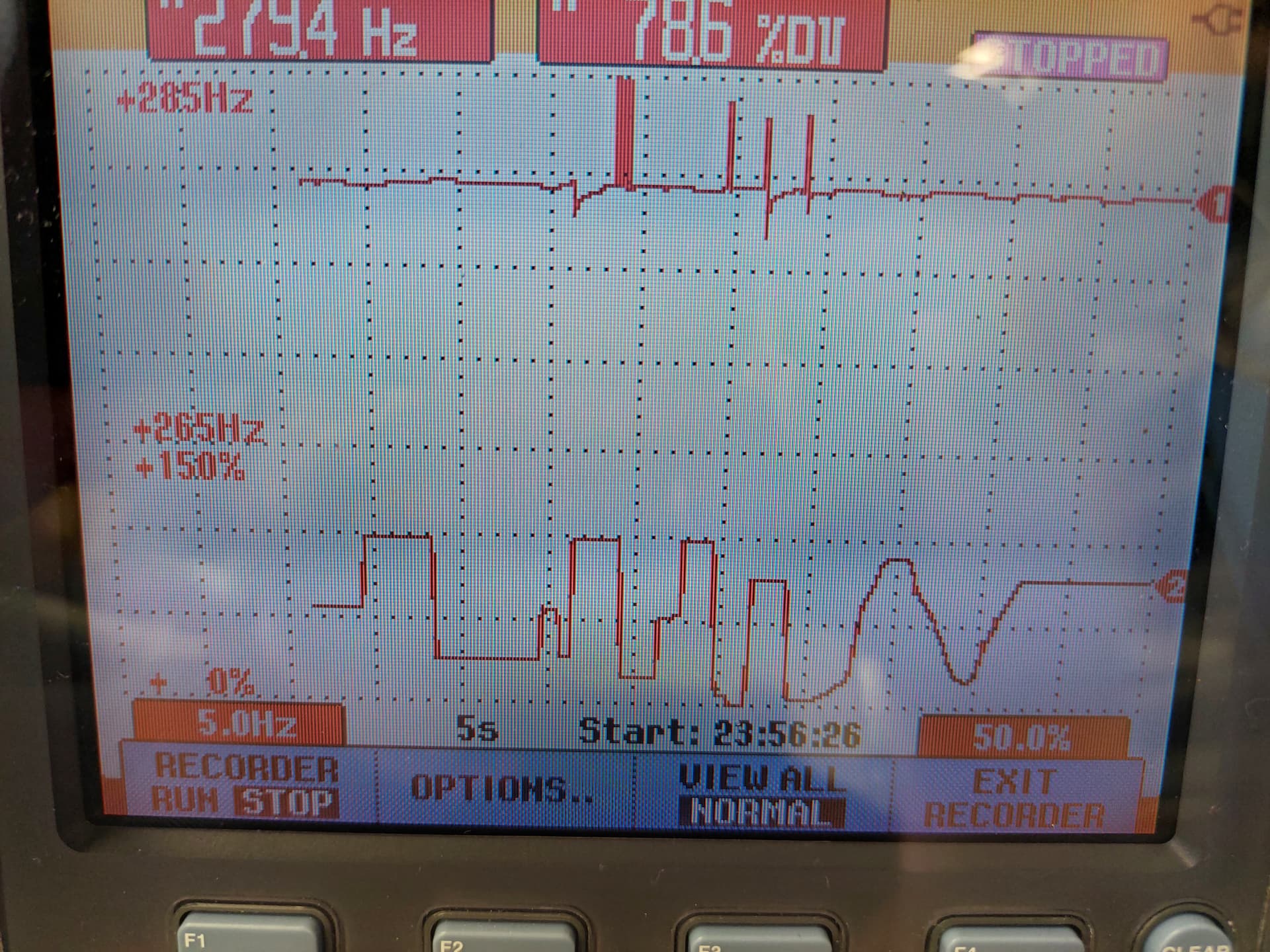
I measured the frequency with my digital storage oscilloscope (DSO).
The frequency is 280,395 Hz Which is pretty close to 280,00Hz
The small deviation is due to the fact that the timer works only with binary numbers as dividers with which you can't create a continuum of exact frequencies like
279,5Hz 279,6 Hz... 280,0 Hz, 280,1 Hz ....
instead there is a certain granularity in the frequencies.

The code has a function that automatically chooses the right values for the registers for a given frequency

The PWM iscreated by a switch-case-break-statement and counter-variables
This creates an infinite pulsetrain of

at 280,395 Hz

// this demo-code belongs to the public domain
// this code demonstrates how to blink the  onboard-LED
// of an Arduino-Uno (connected to IO-pin 13)
// in a nonblocking way using timing based on function millis()
// and creating a pwm-signal "in the backround"
// through setting up a timer-interrupt through configuring timer2

// A T T E N T I O N !    R E M A R K
// some other libraries that make use of timer2 may conflict with this


// start of macros dbg and dbgi
#define dbg(myFixedText, variableName) \
  Serial.print( F(#myFixedText " "  #variableName"=") ); \
  Serial.println(variableName);
// usage: dbg("1:my fixed text",myVariable);
// myVariable can be any variable or expression that is defined in scope

#define dbgi(myFixedText, variableName,timeInterval) \
  do { \
    static unsigned long intervalStartTime; \
    if ( millis() - intervalStartTime >= timeInterval ){ \
      intervalStartTime = millis(); \
      Serial.print( F(#myFixedText " "  #variableName"=") ); \
      Serial.println(variableName); \
    } \
  } while (false);
// usage: dbgi("2:my fixed text",myVariable,1000);
// myVariable can be any variable or expression that is defined in scope
// third parameter is the time in milliseconds that must pass by until the next time a
// Serial.print is executed
// end of macros dbg and dbgi

void PrintFileNameDateTime() {
  Serial.println( F("Code running comes from file ") );
  Serial.println( F(__FILE__));
  Serial.print( F("  compiled ") );
  Serial.print(F(__DATE__));
  Serial.print( F(" ") );
  Serial.println(F(__TIME__));
}


boolean TimePeriodIsOver (unsigned long &periodStartTime, unsigned long TimePeriod) {
  unsigned long currentMillis  = millis();
  if ( currentMillis - periodStartTime >= TimePeriod )
  {
    periodStartTime = currentMillis; // set new expireTime
    return true;                // more time than TimePeriod) has elapsed since last time if-condition was true
  }
  else return false;            // not expired
}

unsigned long MyTestTimer =  0;                   // variables MUST be of type unsigned long
const byte    OnBoard_LED = 13;


void BlinkHeartBeatLED(int IO_Pin, int BlinkPeriod) {
  static unsigned long MyBlinkTimer;
  pinMode(IO_Pin, OUTPUT);

  if ( TimePeriodIsOver(MyBlinkTimer, BlinkPeriod) ) {
    digitalWrite(IO_Pin, !digitalRead(IO_Pin) );
  }
}


const unsigned long pwmBaseFrequency = 16800;
const unsigned long pulseFreq = 280;

volatile unsigned long pwmCounter   = 0;
volatile unsigned long periodCount  = pwmBaseFrequency / pulseFreq;
volatile unsigned long duty80    = (periodCount * 4) / 5;
volatile unsigned long duty25    = (periodCount * 1) / 4;
volatile unsigned long duty50    = (periodCount * 1) / 2 ;


void setupTimerInterrupt(unsigned long ISR_call_frequency) {
  const byte Prescaler___8 = (1 << CS21);
  const byte Prescaler__32 = (1 << CS21) + (1 << CS20);
  const byte Prescaler__64 = (1 << CS22);
  const byte Prescaler_128 = (1 << CS22) + (1 << CS20);
  const byte Prescaler_256 = (1 << CS22) + (1 << CS21);
  const byte Prescaler1024 = (1 << CS22) + (1 << CS21) + (1 << CS20);

  const unsigned long CPU_Clock = 16000000;
  const byte toggleFactor = 1;

  unsigned long OCR2A_value;

  cli();//stop interrupts

  TCCR2A = 0;// set entire TCCR2A register to 0
  TCCR2B = 0;// same for TCCR2B
  TCNT2  = 0;//initialize counter value to 0

  TCCR2A |= (1 << WGM21); // turn on CTC mode
  TIMSK2 |= (1 << OCIE2A); // enable timer compare interrupt

  // the prescaler must be setup to a value that the calculation
  // of the value for OCR2A is below 256
  TCCR2B = Prescaler___8;
  OCR2A_value = (CPU_Clock / ( 8 * ISR_call_frequency * toggleFactor) )  - 1;
  dbg("1 setup: timer ", OCR2A_value);

  if (OCR2A_value > 256) {  // if value too big
    TCCR2B = Prescaler__32; // set higher prescaler
    OCR2A_value = (CPU_Clock / ( 32 * ISR_call_frequency * toggleFactor) )  - 1;
    dbg("setup: prescaler 32", OCR2A_value);
  }

  if (OCR2A_value > 256) { // if value too big
    TCCR2B = Prescaler__64;// set higher prescaler
    OCR2A_value = (CPU_Clock / ( 64 * ISR_call_frequency * toggleFactor) )  - 1;
    dbg("setup: prescaler 64", OCR2A_value);
  }

  if (OCR2A_value > 256) { // if value too big
    TCCR2B = Prescaler_128;// set higher prescaler
    OCR2A_value = (CPU_Clock / ( 128 * ISR_call_frequency * toggleFactor) )  - 1;
    dbg("setup: prescaler 128", OCR2A_value);
  }

  if (OCR2A_value > 256) {  // if value too big
    TCCR2B = Prescaler_256; // set higher prescaler
    OCR2A_value = (CPU_Clock / ( 256 * ISR_call_frequency * toggleFactor) )  - 1;
    dbg("setup: prescaler 256", OCR2A_value);
  }

  if (OCR2A_value > 256) {   // if value too big
    TCCR2B = Prescaler1024;  // set higher prescaler
    OCR2A_value = (CPU_Clock / ( 1024 * ISR_call_frequency * toggleFactor) )  - 1;
    dbg("setup: prescaler 1024", OCR2A_value);
  }

  OCR2A = OCR2A_value; // finally set the value of OCR2A

  sei();//allow interrupts
  dbg("setup: timer done", OCR2A_value);

  dbg("setup",periodCount);
  dbg("setup",duty50);
  dbg("setup",duty80);
  dbg("setup",duty25);
}

unsigned long pwmCount = 0;
const byte PWM_Pin     = 4;
const byte Clock_Pin   = 5;


void setup() {
  Serial.begin(115200);
  Serial.println( F("Setup-Start") );
  PrintFileNameDateTime();
  pinMode(PWM_Pin, OUTPUT);
  pinMode(Clock_Pin, OUTPUT);

  setupTimerInterrupt(pwmBaseFrequency);
  pwmCount = 0;
}

const byte sc_50percentDuty = 1;
const byte sc_80percentDuty = 2;
const byte sc_25percentDuty = 3;

byte dutyState = sc_50percentDuty;
byte pulseCount = 0;
volatile byte pwmState;

void flap() {
  pwmCount++;

  digitalWrite(Clock_Pin, !digitalRead(Clock_Pin) );

  if (pwmCount == periodCount) {
    pwmCount = 0;
    digitalWrite(PWM_Pin, !digitalRead(PWM_Pin) );
  }

  switch (dutyState) {

    case sc_50percentDuty:

      if (pwmCount == duty50) { // if end of HIGH-time reached
        digitalWrite(PWM_Pin, LOW); // set LOW
        pulseCount++;

        if (pulseCount == 11) {
          pulseCount = 0;
          dutyState = sc_80percentDuty;
        }
      }
      break;

    case sc_80percentDuty:

      if (pwmCount == duty80) { // if end of HIGH-time reached
        digitalWrite(PWM_Pin, LOW); // set LOW
        pulseCount++;

        if (pulseCount == 11) {
          pulseCount = 0;
          dutyState = sc_25percentDuty;
        }
      }
      break;

    case sc_25percentDuty:

      if (pwmCount == duty25) { // if end of HIGH-time reached
        digitalWrite(PWM_Pin, LOW); // set LOW
        pulseCount++;

        if (pulseCount == 10) {
          pulseCount = 0;
          dutyState = sc_50percentDuty;
        }
      }
      break;
  }
}


ISR(TIMER2_COMPA_vect) {
  flap();
}


void loop() {
  BlinkHeartBeatLED(OnBoard_LED, 200);

}

best regards Stefan