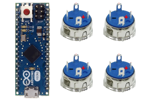
Hello. Im making a button box and i need to wire 8 push buttons with led in matrix. I need the led to be always enabled. Will my wiring diagram work like I need? Thanks in advance

the led built in to your button might require a current limiting resistor and you need to look at how much amps are drawn from those LEDs and if the Arduino can cope with that
for the rest, a detailed doc on the role of the 4 pins is needed
No idea, and as usual the Ali documentation sux. So.
Do you have a switch in hand(i.e. have you bought the thing yet)? If no, Path A. If bought but not in hand, Path B. If in hand, Path C.
A: go find something that's properly documented, Ali, Amazon, or elsewhere
B: wait for it to arrive, then go to C:
C: Step 1, identify which pins are for the LED, and figure out what current at what voltage is needed. Ask for help, if you don't know how.
Step 2, identify which pins are NO, NC, and C, and whether the contact is momentary, or continues when you've released the button. That will determine how you wire the switch, and how your code deals with the switch function.


The switch is in my hand.
The LED lights up when i connect the + and - to the power supply. The voltage drop is 2v and the current drawn 5mA.
The multimeter reacts when its connected like on the image and the switch is pressed


internally it's likely like this

then you wire it the way you want
if you bring current at the entry of the LED but don't have a path to GND until the button is pressed then the button controls the LED
if you connect the Anode to 5V and cathode to GND then it's always on
you should double check that there is no need for a resistor
Ok, so we know
- this is a momentary button, and the button pins are independent of the LED pins
- you have wired this like a 2x4 matrix, as you seem to have 4 connections to one side of the buttons, and 2 common connections to the other side of the buttons
- the LED needs 5mA at 2V; you can calculate the dropping resistor (3V at 5 mA), for a 5V Arduino; it may be that there is an internal resistance, but I don't see evidence of that in your testing so far.
Does that help? Your later question leaves me wondering if you understand matrix, vs individual button wiring.
I'm sorry, I didn't understand much of this image. Can you show me on this image how to connect, or my image is correct?
Yeah.... To wire a 4 pin push button switch, you need to identify the function of each pin. Usually, two pins are for the switch contacts, and two pins are for the LED light. The switch contacts are normally open (NO) or normally closed (NC), which means they are either disconnected or connected when the button is not pressed.
as you want the LED always on, find the 2 pins that are related to the LED ➜ the Anode (+) goes to 5V, the cathode (-) to GND (I would add a resistor)
the other 2 pins are for the switch.
You wire one side to GND the other side to your pin which you set up as INPUT_PULLUP
Il reading this on my iPhone and it’s just a spaghetti dish…
Represent the buttons with their internal icon and show the connections you have in mind
Enjoy your meal
YMMD ![]()
Hi! How should I wire this 12v button to an Arduino? Pins 1 and 2 are for the switch contacts but pin 1 is also for the LED. If i wire pin 1 to an Arduino pin and to a 5v Arduino pin the button won't work. Should I insert a diode somewhere or what? Thank you!


Confusing description. What "battery", what voltage is it made for?
Please post technical documentation.
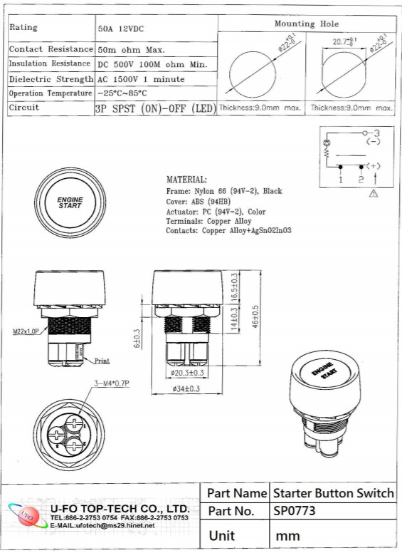
Maybe they have a built-in resistor for use in 12V systems? ("engine start"...)
If that's the case, they could work on 5V, but reduced brightness.
Yeah, it lights up the brightness is too low. If i connect the + pin to 5v on arduino the brightness rise but the switch wont work. Should i remove the resistor?