I was hoping someone knew how to hookup this specific neopixel strand to an uno processor. Nothing online helps because aforementioned neopixel tutorials don't have anything with 4 wires on each end of the strand. Everything shows just 3 connections or 6 for both sides, but nothing on what to do if you have 4. Plus the signal connection is attached to some clip that I haven't seen before. I've been trying to hook this up properly for a while so any help would be appreciated.
Please provide the link where you purchased the that LED strip.
That must be addressable strip using a type of chip that has a clock. Do you know what type of chip is used, or can you find out by removing some of the waterproofing and reading what is on it ?
I don't remember exactly which ones, but they were off amazon and legitimate adafruit strands. This one is 30 LEDs per meter and a 2m roll making 60 LEDs altogether.
Not sure where the chip would be to be honest, the only thing really printed on the strand though is this: 'sj-10060-2811'
Well the WS2811 is an addressable LED driver chip, but that is not a very much help as these can be configured into 12V strips or 5V strips. They normally have three LEDs for each LED count in the software.
If you don’t know what you have in electronics then you are pretty much stuffed as to getting it to work.
Can’t you look through your Amazon orders and see what you actually got?
It is likely that the extra black wire is an extra ground , one to go with the power supply and the other along with the signal.
Hi,
Have a look here;

It looks like the 4 wire needs a controller that has an IR receiver in it.
Tom... ![]()
![]()
![]()
![]()
Does the NeoPixel strip simply have 2 GND connections on each end like this ?

How about you take a 'good' picture of it for us.
Hey thats my job to ask that.... ![]()
![]()
![]()
![]()
![]()
![]()
![]()
![]()

I know what the eletronic components are and how to connect them, the strip I have is just different from what is online even though it's from adafruit. Is there somewhere I could attach the signal and extra ground on an uno or is the clip just for jumper wires?
I definitely didn't get one that connects to a smart phone or has a receiver, just a standard strip I need help wiring. I got a 2m roll of this one https://www.amazon.com/Adafruit-NeoPixel-Digital-Weatherproof-LED-1m/dp/B072QKZG9G?th=1
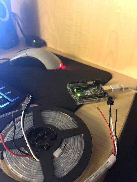
The photograph that you have posted, bad though it is, shows that the strip has the expected 5V, GND and Data In/Data Out connections for each LED with Data Out from one chip connected to Data In for the next chip as expected
Where are you seeing the 4 connections that you refer to in your original post ?
The 4 wires coming OUT of the strip, nothing on the strip itself, edited the photo for clarification

The green arrow is pointing to the wires which the current is flowing to
Measure resistance between both black wires. I bet it's zero.
Reasonably sure that it is as below, I don't see another sensible way.
- Black is GND.
- Red is power.
- White is signal.
I knew that going in, the only thing that I'm having trouble wiring to the uno from this strip really is the signal because it has the black clip on the end of it. It's visible on the end of the black and white wires. It has two holes for the GND and signal inside it, but jumper wires don't really work with it, and it doesn't fit or attach anywhere on the uno. Only thing I could consider was just soldering it straight to a wire and connecting it to a pin that way. Everything else I try is too loose a connection.
Seriously ? ah well we (at least me) misunderstood. I would cut of any connector that came with it (unless you have it's female companion) and use a male header pin on the end. Then with a breadboard i would connect a 470 ohms resistor in series with the data pin to a digital pin of the UNO (2 - 12) and refer to that pin as such in your sketch. The wiring makes complete sense btw. You power the strip with an external power supply and have GND connected to the UNO as well (if it derives it power not from that same power supply)
But the black clip doesn't have to stay on the wire, does it ?