Hi all, what are the options to have a negative voltage to power an op amp from a +12V or +15V power supply and get a voltage of -12V or -15V.
Many op-amps require both a + and a - supply. IS that what you have?
First I will have to read a 0-200mVdc signal with an Arduino UNO and then I have a PWM signal that I will play in an RC filter and then I will need an output signal from 0 to 10Vdc.
Between I thought of using an operational amplifier with a supply of +/-12V or +/-15V to not have a problem, mainly to read the signal from 0 to 200mVdc
Use a charge pump voltage inverter. You can find standalone chips like the old-school 7660 that do this.
If you only need about -4V an Arduino digital output can drive the circuit directly. You can add transistors for higher voltages, but at that point you may as well just get the dedicated chip.
2 Likes
The 0-10Vdc output would be easier to create and much more accurate, using a 10V DAC.
I have an ICL7662 here but I didn't find the maximum current it can supply in the datasheet.
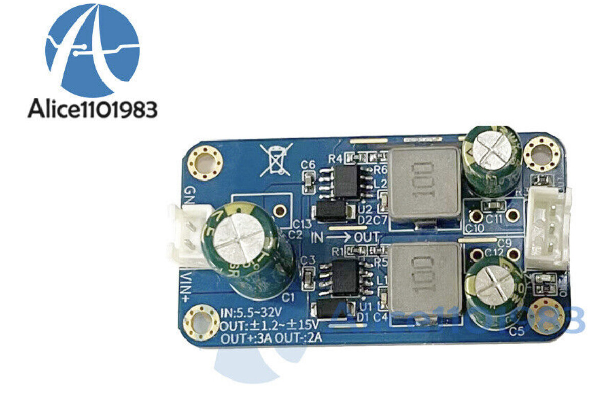
Another thought is to use 2 Hi-link DC-DC converters or similar from 5V to 12V. In one cconverter I use it with 5V input and 12V output and in the other one I use it with 5V input and reversing the output I get -12V
What do you think, have you done or seen something like this?
Normally if I'm doing something like this I just use a +/- DC-DC converter.
Look for a very cheap device known as a "voltage mirror". That supplies the inverse of what ever you power it.
A 555 timer can be configured as a charge pump. With +5V in, it can deliver about -4.5V.
If you only have very basic components such as op amps, I would use one to take your positive voltage and bring it to a negative one.
You just connect Vcc+,Vcc- and V- to your positive voltage and your V+ to the GND. The output will give you the mirror version of your positive voltage (so a negative one...). Not the best solution but works in most cases. Just make sure you're using the right op amp
How much resolution do you need when you read the 200mV input? If you set the ADC for low range, then you'd have 10 bits over a 1.1V range, which is about 1mV per step. You'd then have 186 steps over your 200mV input range. If that's good enough, then you don't need an op amp on the input.
You do need an op amp for the output, but maybe you don't have to have a negative supply. Even the humble LM324 can go down to very near 0 volts, and there are better ones that can drive a voltage almost to the supply rails.
This will not work at all. An op-amp can only output voltages between it's supply rails. So it cannot output a negative voltage by inverting a positive input voltage unless the op-amp is supplied with a negative voltage rail. Which is what you are trying to do to begin with - supply an op-amp with a negative rail.
The charge pump ILC7662 will supply a current of ~10mA and is adequate to generate a negative rail for an op-amp.
You might also want to consider using an ADS1115 as an ADC instead of the Arduino. The highest gain setting provides 15bits over 0-256mV range which is well suited to your input range of 0-200mV. For any solution you devise noise is going to be a problem below 1mV but a well constructed circuit will give you highly linear results from the ADS1115 at around or a little above 1mV without any special techniques.
If you're already using an arduino, you don't need the 555. An output pin will drive a charge pump circuit just fine. However, you're limited to -5V (minus diode drops).
That is true however it will tie up one of the PWM pins and give you only about 3 mA @ -4.3V at best. The 555 has much more output current than a Arduino output pin so 10 mA to the Op Amp would be reasonable.
You are right but how about creating a "virtual ground" ?
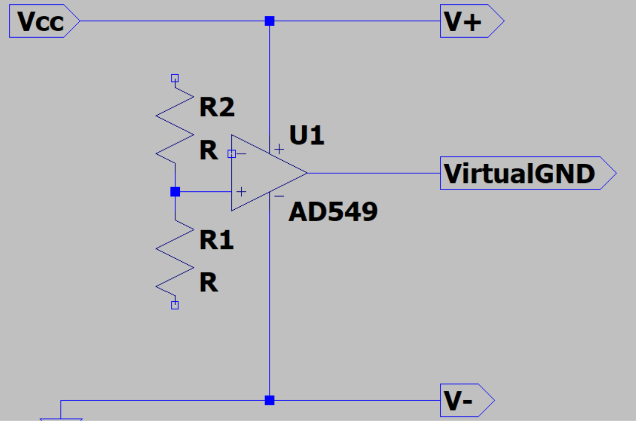
This should work with the aop to give a V+ and V- from Vcc but if you have very different charges connected to V+ and V- it will give asymetric voltage supply so this method cannot be really used in most circuits
I didn't pay attention my circuit isn't finished but I bet you all understand how it works ![]()
This topic was automatically closed 180 days after the last reply. New replies are no longer allowed.