I am using an Arduino Uno with a Motor Shield and two 12 V brushed DC motors (Pololu - Motor with 64 CPR Encoder for 37D mm Metal Gearmotors (No Gearbox, No End Cap)) . To detect the voltage difference two RB-Phi-86 voltage sensors and are externally powered. I am controlling the motors using PID to regulate the speed and PWM. The code that I use to measure the voltage is:
The voltage that I read is not always negative but varies with a pattern I believe it is associated with the PID but I do not understand why it would ever be negative.
I will admit I can't quite visualize in my head based on what you are doing BUT I do see the following:
Voltage_A = (voltageRawA - 512) * 0.073170;
You are subtracting the value of voltageRawA by 512. This variable has a max value of 1024 so it means for anything less than 1/2 Vref you will get a negative number.
So lets assume Vref is 1V. Any reads above 500mV will be positive, any reads below 500mV will be negative; 0V and below would result in a reading of -512, while 1V and above would result in a reading of 512. In between those two values the exact number would vary.
Yes because it measures from -30V to +30V, where 512 bits is equal to 0 volts. But why exactly would it be giving me a negative number or a number less than 512?
Jmok:
Yes because it measures from -30V to +30V, where 512 bits is equal to 0 volts. But why exactly would it be giving me a negative number or a number less than 512?
Because that formula is assuming that the voltage you are measuring is biased at 2.5V with respect to the arduino's power supply. If that is not the setup then yes you will read a negative voltage.
Your reading is correct it is your understanding about what is happening that is wrong.
Thanks for that.
According to the data sheet and the diagram I can not see what you are doing something wrong. As others have guessed if there is zero voltage in then you should get 2.5V out of the sensor.
When the positive and negative inputs are equal, the analog output value is 2.5V.
So to test this remove the wires to the voltage inputs and replace that with a wire connecting the two inputs together. Write a sketch that just prints out the result of an analogue read, you should see a continuous reading of 512.
Reconnect your voltage that you want to measure, and the reading should go up. If instead it gos down then swap the two wires over connected to the voltage input.
So when I connected the wires together it gave me a reading of 509 which is more or less 512, and I have the voltage sensor connected in the proper direction. I am attaching a graph of Power versus time for the blade. Power is calculated as voltage times current. The current is read through the A0 pin and it is not the problem its always positive. The cyclic type pattern is associated with the PID controller I believe, but in my opinion it may drop down to 0 but should never be negative because the PID output range is from 0-255 bits.
Jmok:
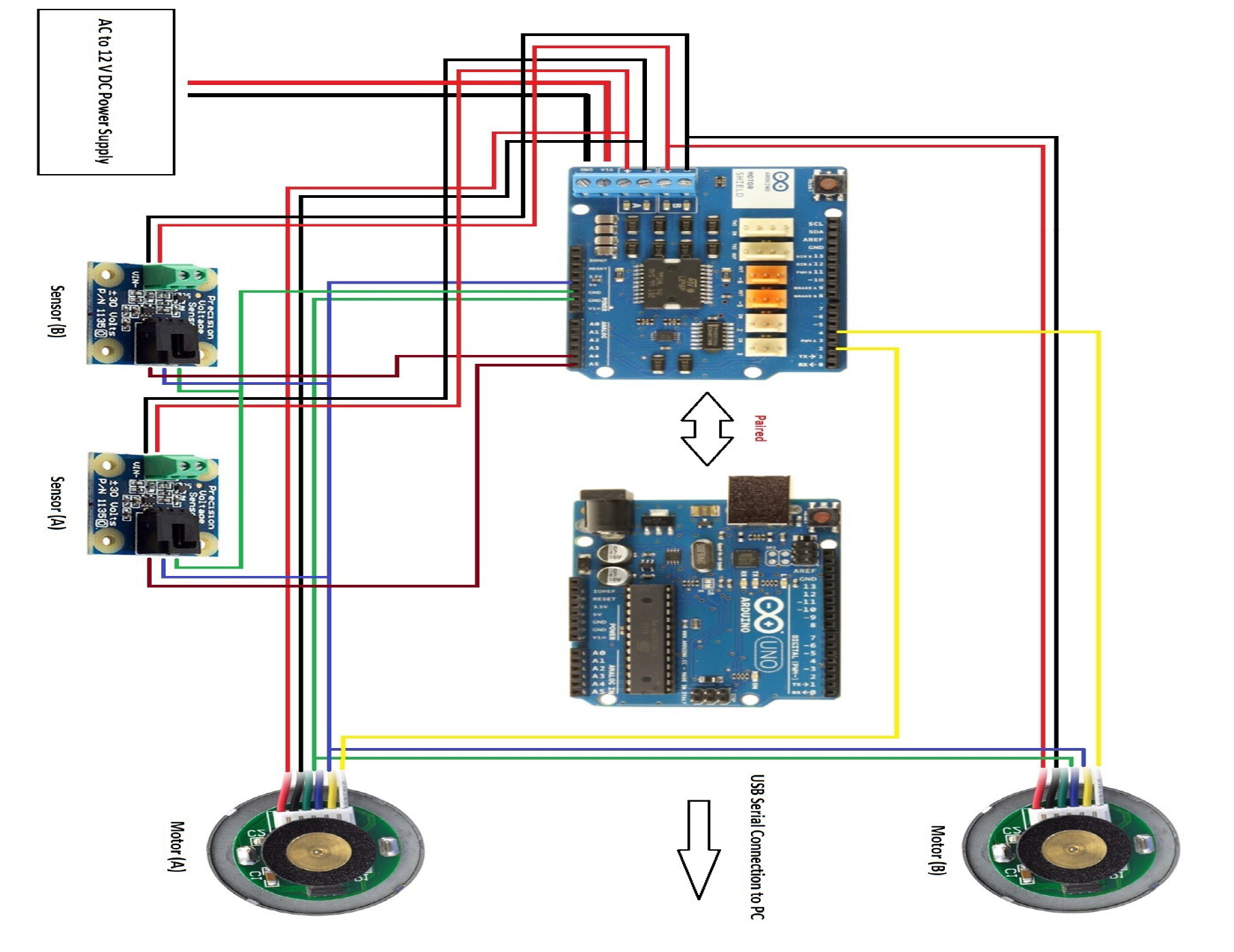
A quick schematic that I drew up before (attached)
Alas that's of little use as a schematic because its a wiring diagram.
Can you sketch the circuit explaining what each wire into the motor is for? A photo
of a sketch that explains the meaning of the circuit is far easier to understand
than a wiring diagram with no signal-names...
[ Also I see no reason for any kind of voltage measuring in a motor control circuit,
except perhaps to keep track of the state of charge of the battery - current measuring
is far more relevant ]
Yea you're right. From Pololu - Motor with 64 CPR Encoder for 37D mm Metal Gearmotors (No Gearbox, No End Cap) the wire colors are explained, but based on the diagram. For the motors, the red wire is power in, black is ground. The Green wire is the ground for the encoder and the blue is the power for the encoder. The yellow wire just sends the signal provided by the encoder, and there is a sixth wire on the motor for another signal for the encoder but it is not used. Basically we are using the encoder to determine the revolutions per minute of the motor and that uses the first encoder signal, and the second encoder signal is generally used to tell the direction but for our setup it only rotates the one direction so the extra wire is unnecessary.
I hope this makes sense and helps, if not ill draw up another diagram.
Thanks for identifying the problem, I tried attaching a diode and a capacitor in parallel with the motor to reduce the noise and the back emf, should this work?
If you are wanting to measure the back EMF in the gaps between PWM cycles, you
may need to consider using a faster ADC than the built-in one (which normally runs in
110us but can be coaxed faster at the expense of accuracy).
A recent board I did used some SPI ADCs to measure a current signal in the gap between
commutation switching using the ADCS7477, which enabled 10 bit sample in a few us
per ADC.
But I'm still confused: You measure rpm with an encoder, yet you want to measure
back-EMF too? Why?