Ok, 16 boards for jraskell, wanderson, copiertalk and florinc should be going out tomorrow...
I sent money for 4 boards, thanks..
Ok, 20 boards for jraskell, wanderson, copiertalk, florinc, and mtd should be going out tomorrow...
6 more going out!
Cookin' with gas!
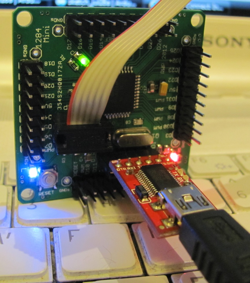
First pic of an assembled 1284 Mini, with AVR ISP Bootload cable and FTDI Basic for sketch downloading.
All the LEDs work ok.
Can't see it here, but the diode across reset pullup resistor got installed backwards and was removed, haven't figured out how to reinstall it yet now that all the headers are installed.
Have some diodes arriving next week, hopefully they will be smaller than the SMB (I think) Schottky we had installed, which was on the big side for the pads anyway.
Not having it didn't interfere with downloading a blink D13 sketch tho.
C1 is also too big, have 0805 size 10uF to put there coming as well.
The LEDs on D0/D1 flash nicely during sketch download, with 1K current limit resistors (vs the 220's I have on the posted PL).
Thanks to my wife for her handiwork installing all the SMD parts for me (and the flipped diode was my fault, told her the wrong end to put the cathode on. Even buzzed it afterwards to check the soldering!)

Nice one.
Rob
Thanks Rob.
Not entirely related but kinda, I built my first SMD 1284 project last night and I was impressed how easy it was to solder the Atmel TQFP-44 package; it has 0.65mm pitch pins so I was able to tack them one at a time, no need to "rake" the soldering iron across all the pins. Had 2 solder bridges that came off easily with wire braid.
Solder bridge / solder flake?

Yes, there seemed to be a little bit of loose debris there. Whatever it was, it blew right off.
What are the consequences of not installing D1? Got my boards today and have the first one mostly assembled (first time soldering surface mount devices), but I forgot to order those diodes. Is that just for reverse power protection, or is it integral to the function of DTR?
I did power it and connect it to my AVRISP MKII, and it was discovered and read just fine in AVR Studio, so it appears to be alive. I'm researching Arduino'izing it now, so I figured I'd throw this question out there while I work on that.
Kudos to you CrossRoads as well. Nice board you put together here. I like how compact it is while still giving access to all the pins.
Thanks!
Glad it is going together well.
Lack of D1 might cause the part to act like its locked up after a reset. Diode was added to Unos for the same reason, keeps chip from thinking it is going into high voltage programming mode.
I bootloaded, then downloaded a sketch, lack of D1 was not a hindrance.
See bottom of Section 3 on page 4 for reset diode discussion.
pg, 2 boards & parts going out tomorrow!
What did I do wrong?
I have an LED on D13 silkscreened on the board as well as the "L" led on the board its self.
I am using arduino ide 1.01
I am using the mighty 1284 bootloader with optiboot.
Standard blink sketch does not blink the LED. but if I change it to
/*
Blink
Turns on an LED on for one second, then off for one second, repeatedly.
  This example code is in the public domain.
 */

// Pin 13 has an LED connected on most Arduino boards.
// give it a name:
int led = 7;

// the setup routine runs once when you press reset:
void setup() {
  // initialize the digital pin as an output.
  pinMode(led, OUTPUT);
}

// the loop routine runs over and over again forever:
void loop() {
  digitalWrite(led, HIGH);   // turn the LED on (HIGH is the voltage level)
  delay(1000);               // wait for a second
  digitalWrite(led, LOW);    // turn the LED off by making the voltage LOW
  delay(1000);               // wait for a second
}
An LED on pin 13 and the "L" led blink as I would expect d13 to if I digitalWrite 13 but I am using 7 in the above sketch.
Are the pins different on the DIP version verses the SMD version. Is there another bootloader I should use?
Thanks. It works and I did burn a bootloader. That was a learning experience in and of its self.
If you selected Bobuino as the board type, then the D#s should be correct.
Going to test mine now to confirm.
Otherwise, not clear to me what you are asking.
That works.
I was selecting the mighty board and the board type instead of the bobduino.
Thanks sir.
Cool.
I just ran this simple sketch on D2 thru D31 one at a time, all pins are connected as marked with Bobuino as board type.
byte testPin = 31;

void setup(){
  pinMode(testPin, OUTPUT);
}
void loop(){
  digitalWrite (testPin, HIGH);
  delay(250);
  digitalWrite (testPin, LOW);
  delay(250);
}
CrossRoads:
If you selected Bobuino as the board type, then the D#s should be correct.
Going to test mine now to confirm.Otherwise, not clear to me what you are asking.
Ah! I was wondering why the silkscreen wasn't matching the Mighty 1284P pin mapping. I should have figured you'd stick with your own Bobuino mapping.
For some reason though, I can't upload with Bobuino selected. I get an avrdude: stk500_getsync(): not in sync: resp=0x00 error. But it uploads just fine when Mighty 1284P 16Mhz is selected. Is there some additional setup step I missed?
I found my own problem. Looked in the boards.txt file and saw that Bobuino uses the Optiboot bootloader, but I put the standard bootloader on my board. Made a 'Bobuino Standard' entry, and that works fine, with matching pinmappings.