Newbie to Arduino; Air Ride Management

Hi Guys!

I am new to the Arduino community, but I want to first start with I am fairly familiar with electronics and circuits (Custom 3D printers, Custom CNC Tables, Custom Drones, etc) but have never dove into the use of an Arduino. I am clueless when it comes to actually coding a program. Most of my experience is from getting a resource off of github, adding my specific values and removing "//" from items that need removed for my application and compile.

Anyways I really want to dive into creating air ride management for my show car. BUT I want to actually document what I am going through with the setup, my circuit, and make it viable for another person down the road to grab my source code, and buy my BOM I list and let it rip. Currently I have not found a single person doing this. Which is appalling to me.

Lastly, if you see something stupid I did, or have a suggestion for improvement; HELP me! My knowledge is subpar for this but I am up for the challenge.

Onto what you clicked on this thread for!

So I have some of the components for the build. This does not matter though as I do not have any code! I had the circuit in my head and decided to first get into TinkerCAD and use their simulation web GUI to construct the circuit and have a ready solution to test my code before I ruin anything. The Circuit is attached. To add, I will have a TFT LCD with 3 buttons to regulate air pressure from Air'd out, show height, and driving height. That is not shown in the Circuit.

A summary of the Circuit in image to clarify:

  • 9V battery represents a Voltage stabilizer to 12V.
  • Arduino Uno is used, will be using Mega 2560 for actual circuit.
  • Sonar sensors represent air pressure transducers; both sensors output a voltage range (0-5v) to represent a value
  • Yellow rectangles are relays
  • The DC motors represent Solenoids. There will be 8 total for this system; 2 per strut. Inlet and Exhaust.

Additionally, if anyone can give me their preference over a LCD with its own microcontroller (like a Nextion) that uses just TX and RX for communication vs a TFT LCD that runs off of the Arduino?

Next I am trying to construct a flow for the program. I have attached as an image as Word can construct a decent flow (or intended to be).

I have done some research to how to code on arduino. It seems very straight forward. I think I can compile the IF commands but I will need to get more familiar with all of the commands as well as understanding on how to create multiple IF command options, and assign those to buttons off of the LCD.

This is all preliminary and cannot wait to show my updates. :slight_smile:

2020-06-15 Update:

So where is the project so far?

I currently have a large list of code, likely redundant in many areas but it is to work with what I can get working, then duplicate to other similar functions.

Nextion Display:

I have code that is talking with my Nextion display that can relay the PSI readings from each corner of the car. I have the pressure converted and set to my sensors, and have been using IR sensors to test on the bench, variation on these analog inputs.

The Nextion display is setup for now to have a main page with the 3 presets, a reset button, and a manual button that navigates to a second page that has buttons for manual adjustment on each corner.

On the Manual Page, the PSI readings (Yellow boxes) are not cropping the image correctly. The ones on the left should look like the ones on the right. I have an warning for each one in the Nextion Editor " Manual FL_PSI.picc Initial warning: Crop area is invalid". Does anyone know how to fix this?

Arduino:

All the relays are mapped to trigger the mosfets to the solenoids in the air manifold.

As stated, I have a pressure value conversion from the analog value input. I also have setup each function for the 3 preset stages to be triggered from the Nextion display.

I REALLY could use some help from anyone familiar with making a Nextion display communicate with Arduino.

Right now, I have the Nextion display able to read from the Arduino values for the PSI values. But I cannot get the Nextion Display to send information to the Arduino to engage the mosfets. This seems like the last big hurdle, or at least until another issue arises when this is completed.

I have attached my code for anyone to please help find my issue? I keep watching the same youtube videos and articles without luck.

Link for Code (Sorry it is beyond 9000 characters) Code

Hardware and 3D Models:

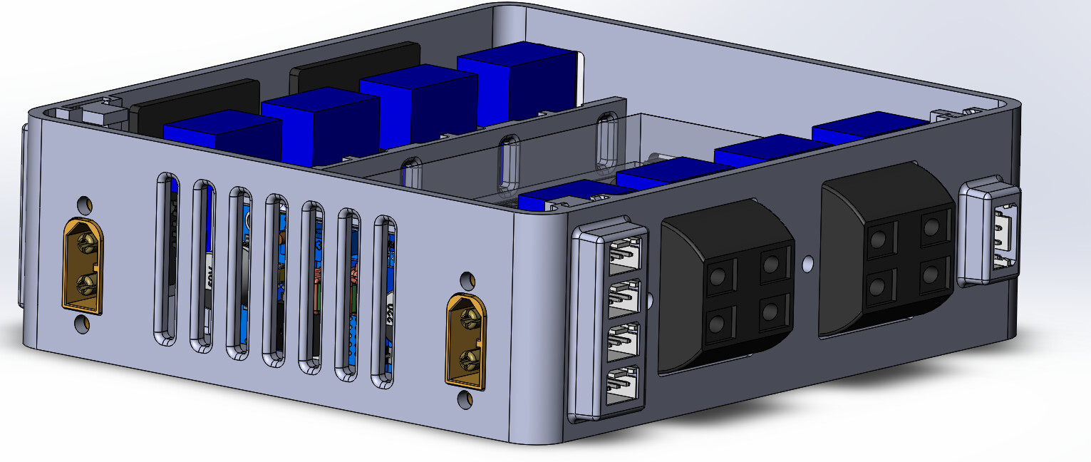
I have been modelling the main housing assembly and have a pretty solid plan for it all. This will house the Arduino, the shield, all 8 mosfets, a buck converter to power the solenoids, and all features for wire management with strain reliefs.

I am solidfying my wiring harnesses with 3 wire cables, and the remaining cables will be restrained inside of braided cable sleeve.

Once the 3D model for the case is finished, I will begin to hook up what hardware I can in the car :slight_smile:

Attached are various photos of the Case and the assembly (minus wires), and Display pages.

Arduino Shield.PNG

Reserved

Hi,
Welcome to the forum.

Please read the post at the start of any forum , entitled "How to use this Forum".
OR
http://forum.arduino.cc/index.php/topic,148850.0.html.
Then look down to item #7 about how to post your code.
It will be formatted in a scrolling window that makes it easier to read.

As all of the forum contributors are around the world, your thread may take up to 24hours the get a response.

Reserving post space preforms no meaningful purpose.

OPs images.

Thanks.. Tom... :slight_smile:

Hi Tom thanks for the pointers.

And sorry I am used to my car forums, a lot of people reserve reply spots in the thread to keep updates at the top of the thread. Bad habit :slight_smile:

Cheers

Hi,
No problem, here you update as the thread progresses.

Tom.. :slight_smile:

General advice for such projects is to start with some simple sketches (programs) that each work with one component. When you have a full set encompassing all your hardware, start combining them.

Don't try to do the whole thing at once unless you enjoy pulling your hair out.

fickert:
And sorry I am used to my car forums, a lot of people reserve reply spots in the thread to keep updates at the top of the thread. Bad habit :slight_smile:

Actually, quite a good idea as long as you make entirely clear what you are doing. :roll_eyes:

What is not considered friendly, is to delete or change information in earlier posts (except to correct the manner of posting code - point no. 7 in the instructions as Tom mentions), as it confuses the interpretation of later advice. Add stuff by all means.

Hey guys thanks. Yeah I try not to delete info. Or if I do, I make a timestamp note explaining why. Or just cross out sections of text.

Anyways I am off to a slowish start but got some good coding so far.

I am finding out that my circuit I originally posted is needing some work, additionally the sonar sensors were not operating like I was hoping them to, ended up using a temp sensor (varying temp is displayed to arduino via voltage range) and I was getting results.

So I was first just testing my code for registering my air pressure transducers I have in the mail. Luckily I found some good sensor input conversion info in the forum that should give me a good baseline for the sensors.

Link for Pressure Sensor

See the attached code:

int delayTime = 250;
int readPin1 = A0;
int FL_Val;
int readPin2 = A1;
int FR_Val;
int readPin3 = A2;
int RL_Val;
int readPin4 = A3;
int RR_Val;
int readPin5 = A4;
int Tank_Val;
int FL_InletPin = 35;
int FL_ExhaustPin = 37;
int FR_InletPin = 39;
int FR_ExhaustPin = 41;
int RL_InletPin = 43;
int RL_ExhaustPin = 45;
int RR_InletPin = 47;
int RR_ExhaustPin = 49;
float FL_Volt;
float FR_Volt;
float RL_Volt;
float RR_Volt;
float Tank_Volt;
float FL_Pressure;
float FR_Pressure;
float RL_Pressure;
float RR_Pressure;
float Tank_Pressure;
void setup() {
  // put your setup code here, to run once:
  pinMode(readPin1, INPUT);
  pinMode(readPin2, INPUT);
  pinMode(readPin3, INPUT);
  pinMode(readPin4, INPUT);
  pinMode(readPin5, INPUT);
  pinMode(FL_InletPin, OUTPUT);
  pinMode(FL_ExhaustPin, OUTPUT);
  pinMode(FR_InletPin, OUTPUT);
  pinMode(FR_ExhaustPin, OUTPUT);
  pinMode(RL_InletPin, OUTPUT);
  pinMode(RL_ExhaustPin, OUTPUT);
  pinMode(RR_InletPin, OUTPUT);
  pinMode(RR_ExhaustPin, OUTPUT);
  Serial.begin(9600);

}

void loop() {
  // put your main code here, to run repeatedly:
  //Pressure Readings and display to LCD
  FL_Val = analogRead(readPin1);
  FL_Volt = (5. / 1023.) * FL_Val;
  FL_Pressure = (0.244379 * analogRead(readPin1) - 25);
  Serial.print("FL PSI:");
  Serial.println(FL_Pressure);
  delay(delayTime);

  FR_Val = analogRead(readPin2);
  FR_Volt = (5. / 1023.) * FR_Val;
  FR_Pressure = (0.244379 * analogRead(readPin2) - 25);
  Serial.print("FR PSI:");
  Serial.println(FR_Pressure);
  delay(delayTime);

  RL_Val = analogRead(readPin3);
  RL_Volt = (5. / 1023.) * RL_Val;
  RL_Pressure = (0.244379 * analogRead(readPin3) - 25);
  Serial.print("RL PSI:");
  Serial.println(RL_Pressure);
  delay(delayTime);

  RR_Val = analogRead(readPin4);
  RR_Volt = (5. / 1023.) * RR_Val;
  RR_Pressure = (0.244379 * analogRead(readPin4) - 25);
  Serial.print("RR PSI:");
  Serial.println(RR_Pressure);
  delay(delayTime);

  Tank_Val = analogRead(readPin4);
  Tank_Volt = (5. / 1023.) * Tank_Val;
  Tank_Pressure = (0.244379 * analogRead(readPin4) - 25);
  Serial.print("Tank PSI:");
  Serial.println(Tank_Pressure);
  delay(delayTime);

  //Over Pressure Safety
  
    if (FL_Volt > 4.0) { 
      digitalWrite(FL_ExhaustPin, HIGH);                                                                                               
    }
    if (FL_Volt < 3.75) {
      digitalWrite(FL_ExhaustPin, LOW);
    }


    if (FR_Volt > 4.0) {
      digitalWrite(FR_ExhaustPin, HIGH);
    }
    if (FR_Volt < 3.75) {
      digitalWrite(FR_ExhaustPin, LOW);
    }


    if (RL_Volt > 4.0) {
      digitalWrite(RL_ExhaustPin, HIGH);
    }
    if (RL_Volt < 3.75) {
      digitalWrite(RL_ExhaustPin, LOW);
    }


    if (RR_Volt > 4.0) {
      digitalWrite(RR_ExhaustPin, HIGH);
    }
    if (RR_Volt < 3.75) {
      digitalWrite(RR_ExhaustPin, LOW);
    }
}

So far I have been bench testing these with some IR sensors to be a temporary replacement for the air pressure sensors (haven't arrived yet) as they output a voltage range for values. Everything seems to check out in the serial monitor.

At the end of the code I have tried to place in a failsafe check for the arduino to look for. This is where one of my first question is.

I am thinking of having this failsafe to check the pressures of each air strut at all times. If the pressure exceeds the 165psi for 3 seconds (avoid driving conditions where I hit a bump and pressure spikes), it will alert for 1-2 seconds, then deflate to a conservative 100PSI pressure. I am just not sure how to go about it exactly. I am on video 17 of Paul Mcworters videos (awesome btw) and don't think we have covered anything to help create this scenario.

Suggestions? I am kind of stumped as of now.