Hi Folks,
I'm a complete newbie (got my first Arduino two days ago) but loving the lessons so far. My interest in Arduino comes from wanting to try a few things with analogue photography equipment.
Anyway, I've been trying to use a hobby motor with the Arduino so I can use Pulse Width Modulation to control and test the speeds. I've been following this video for advice: Arduino Motor Interfacing using MOSFET and PWM - YouTube
I'm using a 2N7000 N-channel MOSFET, so I think the same one as in the video.
I'm not sure of the specs of the hobby motor, but here is the Amazon listing: https://smile.amazon.co.uk/dp/B07KPTC429/ref=cm_sw_r_tw_dp_U_x_eJPaDbE2JGFQN
When I plugged it all in and uploaded very simple code, nothing happened other than the MOSFET heating up (I quickly switched off).
There's nothing wrong with the circuit (I tried inverting the MOSFET connections which completes circuit and runs the motor - even without the sketch running, maybe not a good idea).
Any idea what the issue is? The motor? Something else? Any work-arounds?
FYI - My ideal motor speed is in the vicinity of 72rpm, although I can go a little lower and 2 or 3 times higher potentially with my DIY gearbox (not pictured).
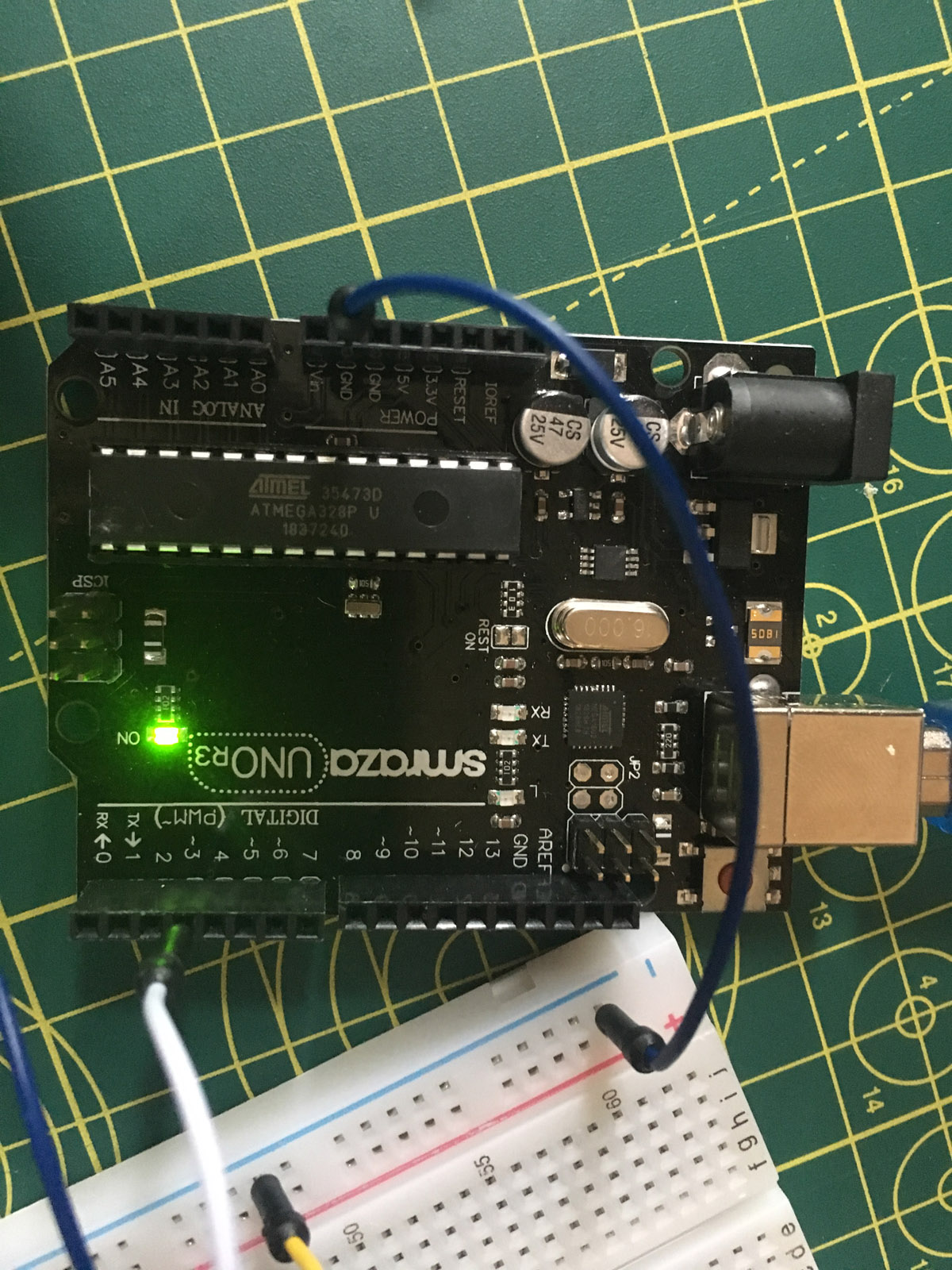
Code below and images attached.
Thanks in advance for any help!
Mike
/*
  Motor with MOSFET

*/

int motor = 3;

// the setup function runs once when you press reset or power the board
void setup() {
  // initialize motor as an output.
  pinMode(motor, OUTPUT);
}

// the loop function runs over and over again forever
void loop() {
  analogWrite(motor, 255);
}
The circuit in the video has a couple of problems. The big one is that there is no flyback diode to shunt the reverse voltage created when the motor shuts off. That voltage is easily high enough to kill a MOSFET. There should (arguably) be a resistor between the Arduino output and the gate to limit gate current while charging the gate capacitance. The 10K pull down resistor will prevent the motor from starting while the motor control pin is floating, before it is changed to output in setup(). The cap will help to filter out motor noise. The resistors and cap are optional, the diode is not. The 2N7000 may already be dead from the reverse voltage spike. Try a new one after adding the diode and carefully checking the circuit.
The 2N7000 is good for 200mA. Is the motor stall (starting) current less than 200mA?
Here is a motor driver schematic and the 2N7000 pin out.
Thanks groudFungus
As I mentioned, I'm very new to this and some of what you've said is beyond my knowledge but I'm going to try and follow - and I really appreciate your input
First off, I have 2x Diode Rectifier (1N4007) that came with my Arduino kit - are these flyback diodes / will these work?
I'm not sure about the mA but it could but similar/same model is rated as: 1500 mA at maximum efficiency, 400 mA at no load - does this mean its too high for the 2N7000. If so, what are other options available (of any sort)?
Cheers
A 1N4007 diode is fine for a flyback. A 2N7000 is way under rated for a motor that draws 1500mA at startup. It likely will not survive. I don't know a proper MOSFET off the top of my head and don't have time to search. Look for a logic level MOSFET with 2A continuous current.
This logic level MOSFET is cheap and will handle any motor you are likely to use. Or for a bit more get it together with a PCB and screw connectors.
Best to add the other parts (at least the two resistors and the diode) shown in the reply #1 schematic.
Also consider the complete Pololu Power Switch, which will handle a pretty beefy motor. You still need a flyback diode across the motor terminals.
Thanks Jremington
Prior to your reply I ordered this module from Amazon - look good to you?
So as per your advice, I guess I should still use the 2x resistors and flyback diode?
Should be coming today and want to make sure I've got it right.
Really appreciate all the advice, always lovely to find a friendly community.
Prior to your reply I ordered this module from Amazon - look good to you?
Not really. The IRF520 MOSFET is not a logic level device. The data sheet for that device lists the Rds(on) at 10V* which means that a 5V output will not fully turn the MOSFET on. The MOSFET linked by jremington is a much better choice. And it will need the resistors and diode.
*from the IRF520 data sheet:
Drain-Source On-State Resistance RDS(on) VGS = 10 V ID = 5.5 -0.27 Ohms
Okay, thanks. A lot of this is going over my head but I'm trying to read-up as much as I can.
From the datasheet, the logic level FQP30N06L also has
RDS(on)
Static Drain-Source - VGS = 10 V, ID = 16 A
On-Resistance - VGS = 5 V, ID =16 A
Is this 10V different to the one I got? Does the second row have importance in this?
Is it worth trying the module I bought, while I wait for the recommended one to arrive?
I just found this video and it would help me if someone could explain how the module I bought is good for the devices this guy uses (I know he makes some mistakes) and not for my hobby motor.
From the datasheet, the logic level FQP30N06L also has
The 2 lines list the on resistance for 10V and 5V gate drive voltage (at 10V 0.027 Ohms and at 5V 0.035 Ohms). What you want to look for when choosing a logic level device is that the Rds(on)e is specified at 5V.
Is it worth trying the module I bought, while I wait for the recommended one to arrive?
You can try it but be aware that the MOSFET will get hot if driven with 5V and it is asked to pass more than a couple of Amps (just like in the video). That is because the on resistance is higher at the lower gate drive voltage. The FQP30N06L will not get hot driving the same load because its on resistance is so much lower.
I see, thanks for the info and quick response.
Your thoughts coincide with this blog post that I can almost wrap my head around and might be useful for others in my position.
That is, indeed, a good blog post. I have bookmarked it for future reference.
Is this 10V different to the one I got?
No, but that is not the best place to look.
What the blog post stresses is that you have to look at the data sheet of the MOSFET for a plot of drain current versus gate to source voltage. For the FQP30N06L sold by Sparkfun, it is

You see that when the gate-source voltage is 3V, the MOSFET is capable of conducting 10A.
You need two resistors to the gate (a high value one to make sure that the gate is grounded when the Arduino pin is INPUT, the low value one to limit the gate current when the pin is OUTPUT). A subtle point that the blog poster overlooked is that the order of the two resistors matters. The order shown in the schematic of reply #1 is the correct one, with R2 to the right of R1.
jremington:
You see that when the gate-source voltage is 3V, the MOSFET is capable of conducting 10A.
Note the graph assumes V_DS = 25V. At 3V gate voltage the MOSFET will dissipate 250W when trying to conduct 10A. It won't survive long.
Thanks for clarifying, Jremington.
So the IRF520 is only capable of conducting around 2A at this voltage?
For interest, I tested the IRF520 module I bought. I've still ordered the recommend FQP30N06L but I'm happy to make mistakes and break things to understand, especially when reading about electronics has quite a steep learning curve - it's nice to do things practically.
The unit worked with the motor in the above config (above an analog value of around 80 - any less wasn't enough to start the motor though would rotate if given a starting "push"). I then tried it without resistors or flyback diode and it seemed to run fine (and cool) with several start and stops at different speeds.
Now I'm not recommending this and I barely know what I'm doing, I just wanted to see what would happen.
The motor torque was nowhere near high enough for my use - not sure if that is a motor limitation or MOSFET related issue or what.
The motor torque was nowhere near high enough for my use -
Since the MOSFET is not turned on it acts as a resistor. Enough of a resistor to limit the current to the motor. You may find that the FQP30N06L, with its much lower on resistance, will provide the current that the motor needs.
Note the graph assumes V_DS = 25V. At 3V gate voltage the MOSFET will dissipate 250W when trying to conduct 10A.
Well gee, by similar analysis, if Vgs were 8 V, the MOSFET would be dissipating 2500W!
Very helpful insight, thanks.
Smajdalf:
Note the graph assumes V_DS = 25V. At 3V gate voltage the MOSFET will dissipate 250W when trying to conduct 10A. It won't survive long.
I wish I knew what this meant, or how to read it on the datasheet.
My next step is reading this post, but I've been busy working my way through Arduino lessons (just reached buzzers and creating melodies with tones).
groundFungus:
Since the MOSFET is not turned on it acts as a resistor. Enough of a resistor to limit the current to the motor. You may find that the FQP30N06L, with its much lower on resistance, will provide the current that the motor needs.
Fair enough, hopefully that will be the case - do you think this would also impact the RPM though? I'm planning on reducing RPM and increasing torque with a DIY gearbox, but this is something else I'm new to. The overall size of this device is important - so perhaps a slower motor is in order, but I want to learn as much as I can with the components and tools I have to-hand so I know what I need.
Thanks everyone for the guidance.
Less resistance will mean that more current will flow. Torque and RPM will increase with higher current. You can control the speed of the motor with PWM, but PWM will reduce average current so also reduce RPM and torque.
I wish I knew what this meant, or how to read it on the datasheet.
It was not a useful contribution, so don't worry about it. My comment was sarcastic.
The relevant and very important characteristic in the FQP30N06L data sheet is this line:
RDS(on) Static Drain-Source On-Resistance | Vgs = 5 V, ID =16 A | 0.035 Ω (typ)
This tells you that if the gate-source voltage is 5V and the transistor is conducting 16 Amperes, the effective internal resistance is 0.035 Ω. The transistor will be dissipating about 16^2*0.035 = 8.5 Watts of heat, which is acceptable if mounted on a good heat sink.
The current draw in your application won't be anywhere near that.