No response from 5611BS 7 segment LED

Hello everyone,

I have the Elegoo Most Complete R3 kit. It came with a 5611BS 7 segment LED. I am trying to run tutorial 3.2 for this component, where it is driven by a 75HC595 IC. They are connected to an Arduino UNO. Following is the code:

//www.elegoo.com
//2016.12.12

// define the LED digit patterns, from 0 - 9
// 1 = LED on, 0 = LED off, in this order:
//                74HC595 pin     Q0,Q1,Q2,Q3,Q4,Q5,Q6,Q7
//                Mapping to      a,b,c,d,e,f,g of Seven-Segment LED
byte seven_seg_digits[10] = { B11111100,  // = 0
                              B01100000,  // = 1
                              B11011010,  // = 2
                              B11110010,  // = 3
                              B01100110,  // = 4
                              B10110110,  // = 5
                              B10111110,  // = 6
                              B11100000,  // = 7
                              B11111110,  // = 8
                              B11100110   // = 9
                            };

// connect to the ST_CP of 74HC595 (pin 3,latch pin)
int latchPin = 3;
// connect to the SH_CP of 74HC595 (pin 4, clock pin)
int clockPin = 4;
// connect to the DS of 74HC595 (pin 2)
int dataPin = 2;

void setup() {
  // Set latchPin, clockPin, dataPin as output
  pinMode(latchPin, OUTPUT);
  pinMode(clockPin, OUTPUT);
  pinMode(dataPin, OUTPUT);
}

// display a number on the digital segment display
void sevenSegWrite(byte digit) {
  // set the latchPin to low potential, before sending data
  digitalWrite(latchPin, LOW);

  // the original data (bit pattern)
  shiftOut(dataPin, clockPin, LSBFIRST, seven_seg_digits[digit]);

  // set the latchPin to high potential, after sending data
  digitalWrite(latchPin, HIGH);
}

void loop() {
  // count from 9 to 0
  for (byte digit = 10; digit > 0; --digit) {
    delay(1000);
    sevenSegWrite(digit - 1);
  }

  // suspend 4 seconds
  delay(3000);
}

Here is how I have connected it:

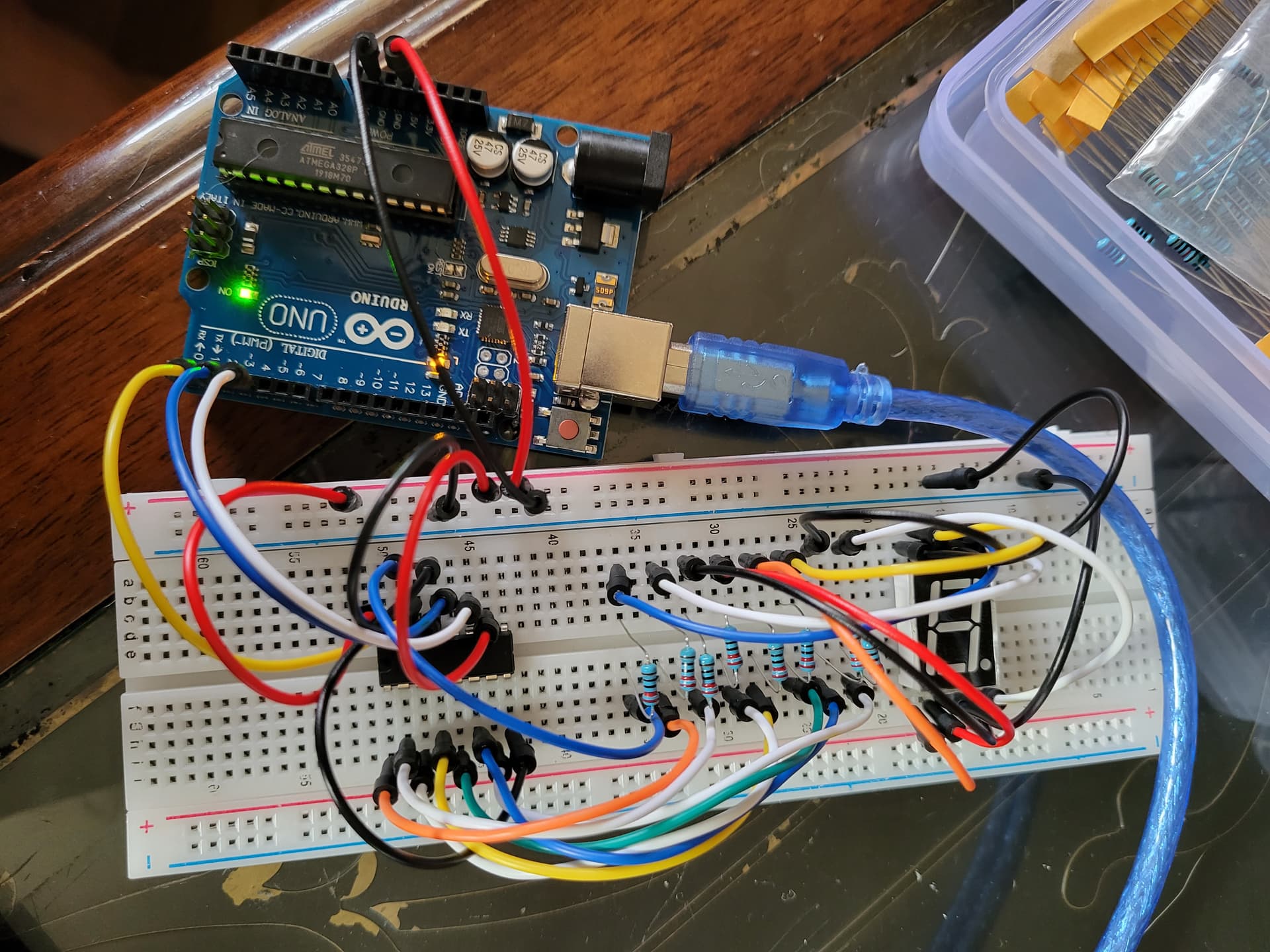
None of the segments are lighting up. I have tested with a voltage meter and get a 5v read across the LED for several different inputs to the ground opposite the LED, so it seems that current is running through it. I can also replace selected leads to the LED with single LEDs and they do light up in time with the code turning them on and off. So it seems to work perfectly with single LEDs. I have an image of this running too if you want to see but again I can only embed one image.

What am I doing wrong? If it is relevant, when I got the kit the pins on this component, and also the similar four digit LED, were bent out of place and I had to bend them back to the correct positions. I am having a similar issue with the four digit LED not lighting up as well.

Thank you so much in advance for any help!

Here is the schematic:

Here it is running with single LEDs swapped in for two positions. It also works for all of the positions if I swap them all.

Hi

ops , something was wrong...

Hi

According to the datasheet this display is common anode.
GNS-5611BS, GNS-5611BS Datasheet, GNS-5611BS PDF - G-NOR see 5611Bx schematic.

Test it with your display.
Unplug all wires that go into it.
Then connect pins 3 and 8 of the display to +5V
Then, with a resistor like the one you are using, connect one end of the resistor to the GND and the other end to connect to pins 1, 2, 4, 5, 6, 7, 9 and 10, one at a time.
If each segment should light up it confirms that your display is common anode and will not work with the 74HC595.

For your project you need the 5611Ax.

1 Like

Oh wow. Thank you so much. Yeah this kit also had a problem with the RGB LED also being common anode when the instructions were common cathode so that makes total sense. This kit definitely has some issues with the expected parts being swapped out for other ones that don't work per the instructions. :stuck_out_tongue: I guess I will need to order either a 5611Ax or a common cathode 7 segment OLED.

You rule!

-Kenji

Okay I did as you said and can confirm that the elements all light up. Thanks again!!!

One last thing I noticed. If I switch the 3 and 8 pins on the LED to +5v (instead of gnd in the schematic), then I invert all of the bits (bitwise compliment) for each number, then it works fine.

i.e. B11100000 becomes B00011111

Aside from a lack of code clarity from not doing it the correct way, are there any other issues with just handling it that way? Could it damage anything? It seems to be running fine.

-Kenji

Yes, it´s true.

These pins don't seem to be the connections you have in the photo. They look like 1, 2, 3 to me, but hard to tell. 1 is already used for the Serial port.

However, if it works then all is good.

Hi Marco,

Thanks for noticing that and letting me know. If you look there is a little gap in the leads on the board between the 7 and 8 pin. Then if you count back from there you can see that the contacts are correctly in the 2, 3, and 4, pins. It really does look like 1-3 though. I will try to get a better angle on the photo next time I post something here so it isn't so misleading.

-Kenji

This topic was automatically closed 180 days after the last reply. New replies are no longer allowed.