Hi, I am new to arduino, I am making a diy weather station. I have figured out how to run a dht22 with my NodeMCU 8266 board, and have utilized the Blynk programming structure. I am not a newbie to electronics, but ill admit this project has led me to become a script-kitty... lol.
I am looking for help in how to add my HMC5883L magnetometer/compass and my wind sensor device rev. C to my sketch, i used the Blynk_DHT22 sketch to do the initial setup. the wind sensor is from Modern Device. Oh and i noticed that both of these new sensors use I2C for communication so i will need to figure out how to sequence both to use the bus but not sampling at the exact time. the compass only needs to have 8 cardinal points for read out. I am not utilizing a display so the output will be seen on my blynk app as a single value.
I understand there are plenty of resources for most likely all of the sensors and board i am using on this project, but i would still like guidance and help putting this together. thanks to anyone willing to help out.
You are welcome on this forum! You are working on an informatic project and what is most needed in an informatic project is information imagine: do the other users here in the forum have a clear picture of what you are trying to do?
To speed up finishing your project you should invest some time into writing additional information I'm 100% sure that this WILL speed up finishing your project.
So please go through this checklist and if you find an item you haven't posted yet post it
did you write which exact type of microcontroller you are using?
description of your programming skills and knowledge
description of your knowledge about electronics
description of the functionality you want to have written in normal works avoiding programming terms
do you have an oscilloscope? Yes / No
do you have a digital multimeter (DMM) Yes / No)
your age
did you post your complete sketch?
if relevant did you post a link to a datasheet of each component you are using?
if relevant did you post a handdrawn schematic or your wiring?
if you got a compiler-error. Did you post the complete compiler-output into a code-section?
If you don't post all this information because you want a "quick answer" to your detail problem It is very likely to turn out that all that happens is having mutliple waiting-times with mutliple asking back for details until the other users do have a clear picture of what you want to do.
You should post code by using code-tags
There is an automatic function for doing this in the Arduino-IDE
just three steps
press Ctrl-T for autoformatting your code
do a rightclick with the mouse and choose "copy for forum"
Nothing to figure out there. There's no reason the two sensors can't be sampling at the same time. I think they are both relatively smart sensors that can be sampling continuously and independantly from each other and the Arduino. No possibility of them using the bus at the same time. I2c bus uses a master-slave arrangement, and slaves only speak when spoken to by the master (the Arduino).
#include <Blynk.h>


/*
  WARNING :
  For this example you'll need Adafruit DHT sensor libraries:
    https://github.com/adafruit/Adafruit_Sensor
    https://github.com/adafruit/DHT-sensor-library

  App project setup:
    Value Display widget attached to V5
    Value Display widget attached to V6
 *************************************************************/

/* Comment this out to disable prints and save space */
#define BLYNK_PRINT Serial


#include <SPI.h>
#include <ESP8266WiFi.h>
#include <BlynkSimpleEsp8266.h>
#include <DHT.h>

// You should get Auth Token in the Blynk App.
// Go to the Project Settings (nut icon).
char auth[] = "         ";


// Your WiFi credentials.
// Set password to "" for open networks.
char ssid[] = "         ";  //Enter your WIFI Name
char pass[] = "        ";  //Enter your WIFI Password


#define DHTPIN 2          // D4 pin


// Uncomment whatever type you're using!

//#define DHTTYPE DHT11     // DHT 11
#define DHTTYPE DHT22   // DHT 22, AM2302, AM2321
//#define DHTTYPE DHT21   // DHT 21, AM2301


DHT dht(DHTPIN, DHTTYPE);
BlynkTimer timer;


// This function sends Arduino's up time every second to Virtual Pin (5).
// In the app, Widget's reading frequency should be set to PUSH. This means
// that you define how often to send data to Blynk App.

void sendSensor()
{
  float h = dht.readHumidity();
  float t = dht.readTemperature(true); // or dht.readTemperature(true) for Fahrenheit

  if (isnan(h) || isnan(t)) {
    Serial.println("Failed to read from DHT sensor!");
    return;
  }
  // You can send any value at any time.
  // Please don't send more that 10 values per second.
  Blynk.virtualWrite(V5, h);
  Blynk.virtualWrite(V6, t);
}

void setup()
{
  // Debug console
  Serial.begin(9600);

  Blynk.begin(auth, ssid, pass);

  dht.begin();

  // Setup a function to be called every second
  timer.setInterval(2000L, sendSensor);
}

void loop()
{
  Blynk.run();
  timer.run();
}
Have you got test sketches working with your 2 new sensors? If not, that's the next step. Focus on one sensor at a time and get a test sketch working. No need for Blynk yet, just sending output to serial monitor. Once those are working, post them here. Then you can think about integrating them with your Blynk sketch.
That wind sensor is not i2c. Were you planning to use an i2c adc module of some kind between the sensor and the Arduino?
The sensor needs 2 analog inputs and you have only one. So you will need either an external adc module, or an analog multiplexer. Either way, the example sketch provided by Modern Devices is written for a 5V Arduino with at least 2 available analog inputs. So that's going to take some fettling.
i am using a NodeMCU 1.0 (ESP-12E module) in the ESP8266 format. same setup as one in picture. I am using Arduino 1.8.15 windows store app version 1.8.49 IDE. My programming skills are basic. My experience is with soldering and building circuits but not "programming" them. i wont get too much into it but i work in the electrician community. I have a digital multimeter but dont have a oscilloscope. I am 31 yrs old.
My programming and electronics background is elementary level, but i tend to dive deep head first into projects. I started recently with a Raspberry Pi Zero W but that project has stalled since i need time to spend learning the ins and outs of the main board and that i don't have time for at the moment. My experience and expertise is set more toward the diy solutions and increase of efficiency, with an emphasize on lol making things way more complicated than they need to be. Automation is a big deal for me. An example is the ongoing project with v3 coming soon of my hot air window exchanger for my vehicle. its now solar powered and temp controlled and will soon have a new battery pack able to reliably run all night if need be.
Put it simply again and a good example, my work bench is in my room, if im not sleeping or at work im at my work bench building the next project. I understand principles of different subjects but i am no expert in any of them.
while using my ESP8266 utilizing the Blynk Legacy app on my mobile, which allows me to easily add a communication dashboard that i can utilize away from my home, i want to create a home weather station. I have a project box that will hold all the electronics and the box will also have solar on top to recharge the batteries as the ESP8266 uses very little mah over a 6hr daylight time frame.
utilize the DHT22 AM2302 Temp/ Humidity sensor with a 3-pin breakout already attached from manufacture. This i have already done in the sketch i have uploaded and posted. I have it attached to 3v3, GND, D4 pins on the right side of the board. it is utilizing a Blynk sketch base to allow communcation to the remote Blynk server.
utilize the Wind Sensor rev. C to calculate wind speed. I will have its sensing unit portion of the board poking out of the box facing toward air flow, since the whole box will be the weather vane and will rotate on my diy bar stool swivel mount utilization attached of course to a pole.
utilize the magnetometer GY-271 HMC5883L sensor board to sense compass direction. relay that info to the Blynk server via the sketch on the ESP8266 board. This sensor will be preliminary mounted inside the project box at the top most portion to move it as far away from electrical noise and any interferences. I dont know if that will be enough, if needed i have 20cm breakout jumper wires that i can use and attach the board to a extended platform out the top of the unit to increase accuracy. i will just have to build a small box for it to be housed in.
This is option 1 of my power boards that can feed my battery pack which in turn will supply constant power to my weather station. the biggest goal of the project and its sensors was not to have to require the use of an external high voltage need for a reed switch wind sensor spinning cup design. the fall back option that i have is this: https://www.amazon.com/gp/product/B088QFMCMV/ref=ppx_yo_dt_b_search_asin_title?ie=UTF8&psc=1
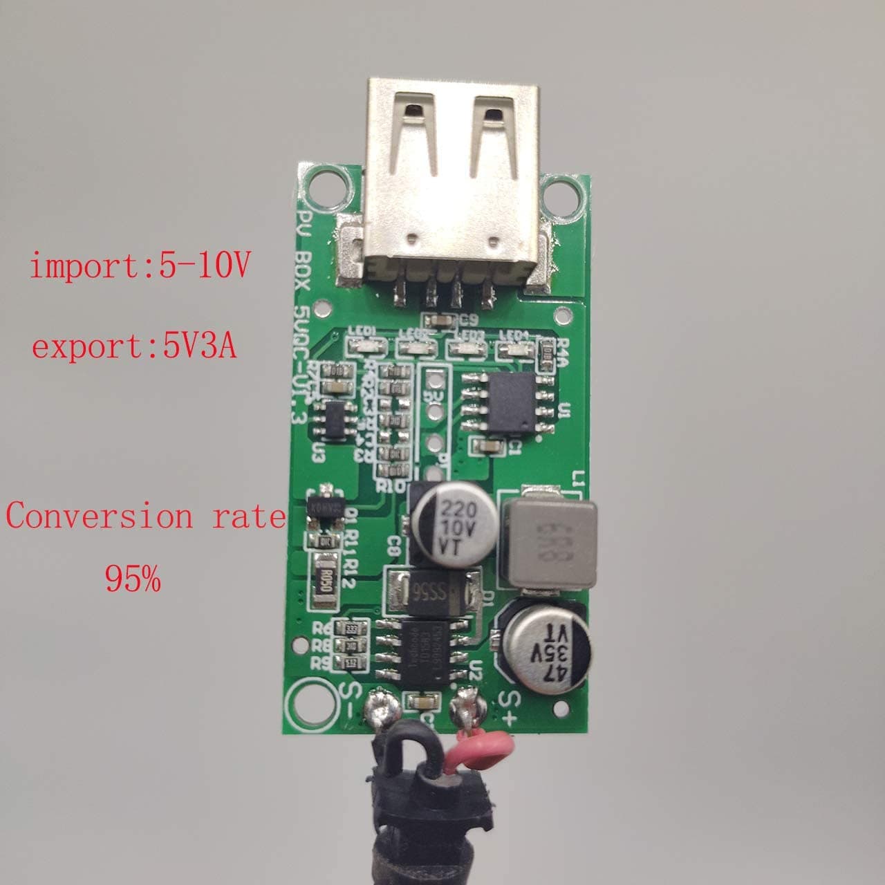
This second board is one ive had for awhile and its ok, but with one major dilemma... it will not restart the 5v output if the battery dies and solar is reapplied and charging the system. I dont know if it can output 5v via the pins and accept solar input at the same time so this will be option 2 but a good idea since i wont have to have a bunch of seperate circuits for a battery to accept charge and discharge and 5v regulate the output.
just seeing this. ok i figured i might need to backstep a bit and utilize local serial first before incorporating Blynk setup, and i see your other reply on the wind sensor utilizing analog and not I2c, hmmm... I dont have any other boards, just those that i have listed.
I suspect nothing you have listed gets around the problem of having only one analog input. In theory, one of those two inputs is used to measure the ambient temperature, I think. So you might think you could rely on the dht22 to provide that, and so need one less analog input. But that wasn't how the wind sensor was designed to work, and trying to use some other temp sensor could screw up the wind speed readings badly.
I would recommend an ads1115 module. This adds 4 additional analog inputs, and considerably better accuracy than the nodemcu's built-in analog input. Plus, it is an i2c device, so can share the same pins as your other sensor, and effectively turns the wind sensor into an i2c device.
How many exactly? I would estimate around 80mA * 6hr = 480mAh. But over the remaining time when your panel its not generating much (18hrs), that's 1460mAh. The capacity of a 14500 size li-ion battery is around 800mAh, so I think you may need a bigger battery? To make things worse, your battery module boosts ~3.7V up to 5V output, so will be drawing at least 110mA from the battery to provide 80mA output, even if it's close to 100% efficient (which, of course, they never are). The nodeMCU will then regulate that 5V down to 3.3V, wasting a third of the energy as heat.
why that? The I2C-bus needs just 2 IO-pins GPIO4 as SDA and GPIO5 as SCL
GPIO 12,13,14,15,16 are free usable.
If the IO-pins don't need to create high-speed bitbanging or high-frequency PWM you can use I2C-Io-expanders like the MCP2307-16-IO-Pin-Expander. As the MCP2307-expander is an I2C-device it gets connected to IO-pin 4,5 too. That's the main purpose of using a bus. sharing IO-pins.
best regards Stefan
Since the weather station is only going to be used by myself, i think i could live with having a schedule setup where the nodemcu goes into deep sleep during the time that i sleep at night. I dont need to know the weather 24/7. Lol
Hmm i should look into running the board from 3.3v if thats possible. I could use a simple circuit to take a "standard" lipo battery 3.7v down to 3.3v. If not possible and it requires 5v from usb then i will figure out a better solution. I was planning on using my 10,000mah protected lipo with the project, the solar panels im using are 5v at 500mah "rated" lol. I will use 2 in parallel to maximize my output.