Noob question about Motor Shield connection - pics

Hello

About to attempt my project this weekend
Using the motor shield the connections are basic that’s no problem

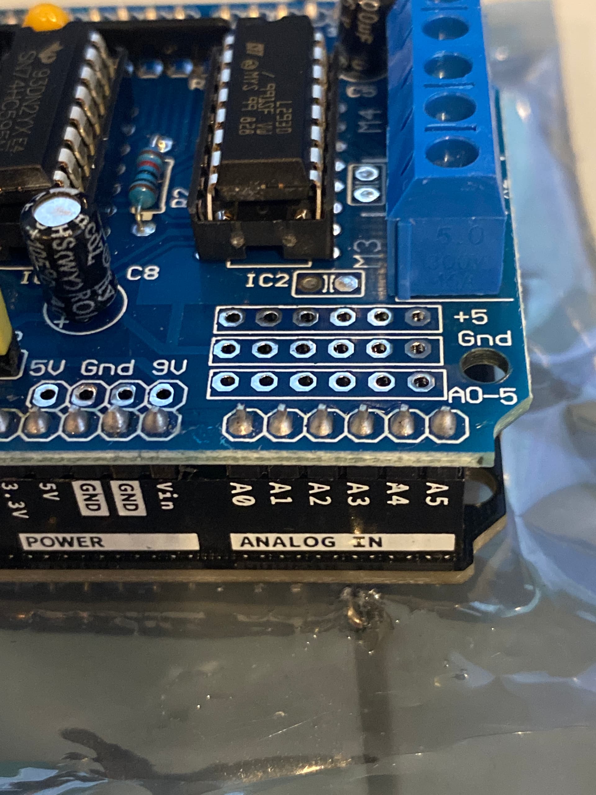
My issue is connection to the analog pins or any other pins that the shield connects to the Arduino to.

If I say use Analog A1, as pictured, do I solder my connection to the A1 “blob” of solder currently in that input? Sorry it’s a stupid noob question. Also , what are -“” the non soldered open connections right above it? There’s about 18 of them?

Thank you in advance

Yes, You can solder a wire the the blob. I advice You to have the shield plugged into the controller in order to keep the pin in the proper position.
That is an economy design of the shield. Some shields at least provide a pin pointing up on the shield, to connect to.

Wouldn’t A1 names on the board just solder to the A1 blob right above it?

Yes. It's surely just a straight pin through the shield . I also don't think the shield is using the A1 pin either. Go ahead!

Thank you for your quick response , will five into this attempted project this weekend! appreciate it

Sometimes there's a match, somebody is listening when the question is asked. Usually the forum helpers here handles questions fast.

Check with your meter. I suspect that the row of empty holes above the A0 to A5 pins are for you to solder to and are actually A0 to A5 too.

The others in that block appear to be multiple ground and 5V points.

1 Like

I missed that.
A possibility to solder pins and use labb cables to breadboard etc...

so i can use either hole or use the empty one, or use the one with solde already in it? sorry for the noob questions i am just new learning this board and first project ahead.
im not using breadboard connections just an audio line coming to it
thank you in advance!!

Yes. As @wildbill said, use a DMM and verify the connection between blobs and holes. He's surely right.

This topic was automatically closed 180 days after the last reply. New replies are no longer allowed.