NOT gate output to switch a MOSFET - not working.

Hi All,

I was wondering if I could ask for some help, I'm building a parachute actuation system for a high altitude balloon and wanted to include something which would deploy the main parachute if the Arduino battery failed and so could not deploy the parachute when a given set of conditions are met.

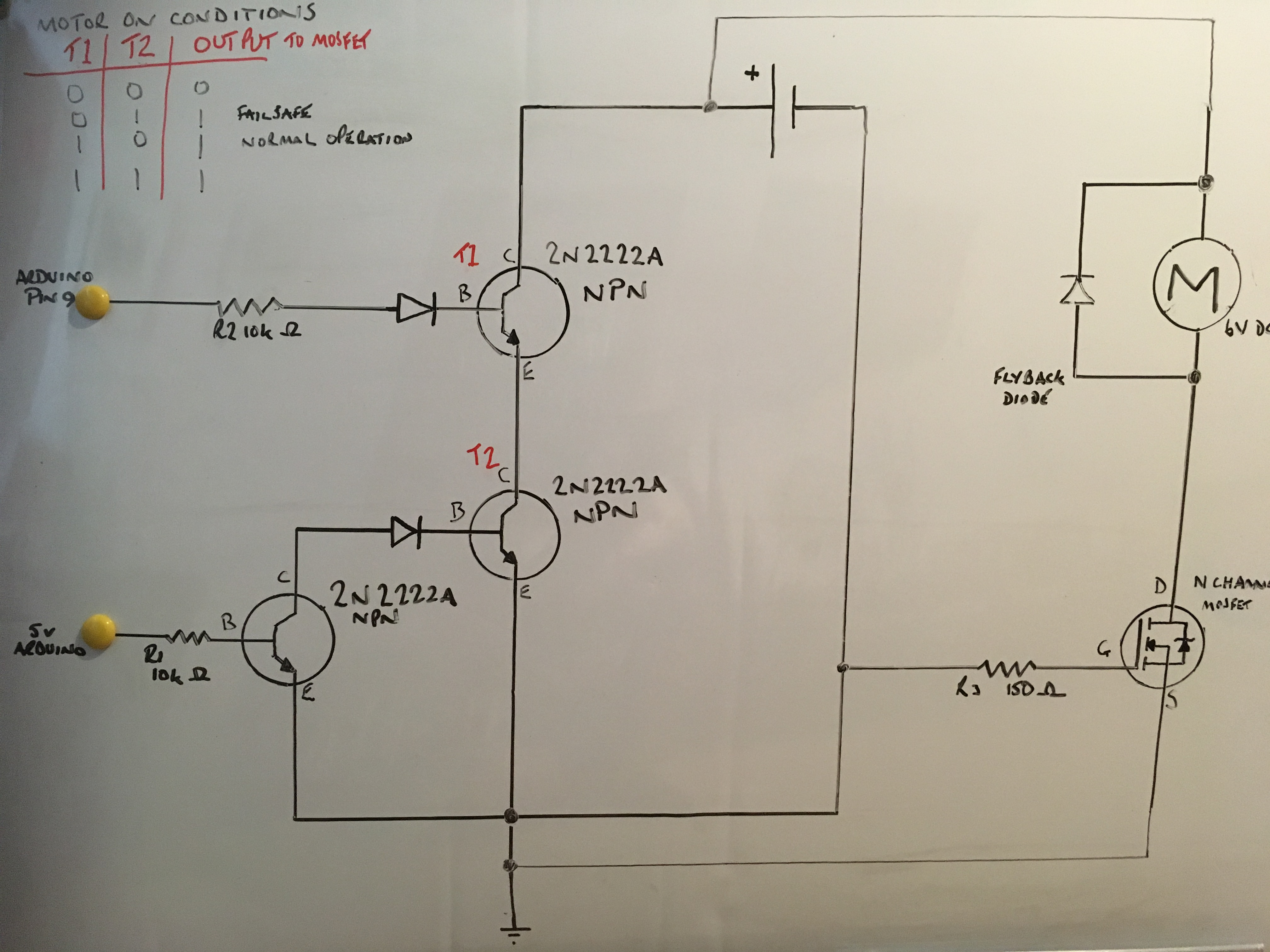
In the final version, an Arduino would write the signal line to the MOSFET high when a given set of conditions are reached, this would switch on a separate power circuit running a DC motor, the motor would withdraw a pin from the parachute container and deployment would commence.

I'm alsoo running a temperature sensor and recrding an averaged reading to an SD card - this work well.

I've used a transistor with it's base connected to the 5v rail powered by the Arduino, the collector is connected to the separate battery that is running the DC motor. If the Arduino battery dies, the transistor base becomes 0 and the output become 1, I thought could use this to switch the MOSFET.

In the prototype, the motor is replaced with an LED to demonstrate actuation and the NOT gate has an LED to comfirm that it switches properly when the USB cable from the Arduino is disconnected from the computer. Actuation is simulated by using a momentary button, when it's pressed, the LED in the MOSFET power circuit should light. If the power to the Arduino is cut, the LED connected to the collector should light demonstrating the transistor has switched as a result of 0 on the base.

I've attached two wiring diagrams:

No1: Simply demonstrates that the MOSFET circuit switches when the button is pressed and the NOT gate LED lights when the USB cable is disconnected. This work fine.

No2: Shows a white wire connecting the collecter of the NOT gate to the signal pin of thhe MOSFET - I thought this would switch the MOSFET when the USB cable was withdrawn, seems not.

What the 2nd circuit does/does not do:

LED in the MOSFET circuit doesn't light when the momentary button is pushed
Neither the MOSFET LED or the NOT gate LED light when the USB cable is disconnected.

Code below is not the final version, it's merely to test the above.

#include <Wire.h>
#include <SPI.h>
#include <SD.h>

/*Parachute release failsafe prototype.
 * This prototype substitutes an actuator for an LED which is powered by a separate 19650 3.7v battery controlled by the Arduino via a MOSFET.
 * A NOT gate has it's signal pin wired to 5v Arduino pin, should the Arduino power fail, the NOT gate supplies a signal to the MOSFET to energise the LED.
 */

/* Micro SD Board pins connnection
  Connect the 5V pin to the 5V pin on the Arduino
  Connect the GND pin to the GND pin on the Arduino
  Connect CLK to pin 52
  Connect DO to pin 50
  Connect DI to pin 51
  Connect CS to pin 53

  TMP36 - Temperature sensor
  Connect Signal Pin to A5
*/

File myFile;                    //SD card

const int temperaturePin = A5;  //TMP36 Pin Set

int buttonState = 0;

void setup() {

  Serial.begin(9600);           //Begin serial communication at 9600bps

  //SD.begin();

  pinMode(53, OUTPUT);
  pinMode (9, OUTPUT);
  pinMode (8, INPUT);                          //button to switch MOSFET on

  if (!SD.begin(53)) {
    Serial.println(F("initialization failed!"));
    return;
  }

  Serial.println(F("SD Card Initialised!"));   //Startup Confirmation to Serial Monitor.
  delay(2000);
}

void loop() {

  buttonState = digitalRead(8);               //Button push simulates signal from Arduino to the MOSFET to initite parachute deployment (or switch on LED in testset up).
  if (buttonState == HIGH) {
    digitalWrite(9, HIGH);
  }
  else {
    digitalWrite(9, LOW);
  }


  float voltage, degreesC;
  voltage = getVoltage(temperaturePin);
  degreesC = (voltage - 0.5) * 100.0;

  Serial.println(degreesC);

  myFile = SD.open("hab.txt", FILE_WRITE);            //Write average temp from TMP36 to SD card.
  if (myFile) {
    Serial.print(F("Writing to test.txt..."));
    myFile.println(degreesC);
    myFile.close();
    Serial.println("done.");
  }
  else {
    // if the file didn't open, print an error:
    Serial.println(F("error opening test.txt"));
  }
}

float getVoltage(int pin)
{
  float volts = 0;
  for (int i = 0; i < 1000; ++i)                   //take average of 1000 readings
  {
    volts = volts + analogRead(pin); 
  }
  volts = volts / 1000;

  return (volts * 0.004882814);                   //return volts
}

I hope this all makes sense, apologies if I haven't made the request in quite the right way, happy to provide further info if required. Thanks for looking though.

Best wishes

Phil

I've attached two wiring diagrams:

Yes but in order to see what your circuit is doing we need to see a schematic not a physical wiring diagram.

No2: Shows a white wire connecting the collecter of the NOT gate to the signal pin of thhe MOSFET -

That is not what I see!

What I see is a white wire going into some sort of external board to a pin. The resolution of the image is too low to make out what the pin is labelled. I can not see a not gate at all in that layout.

Hi,

Can you please post a copy of your circuit, in CAD or a picture of a hand drawn circuit in jpg, png?

Thanks.. Tom.. :slight_smile:

Thanks for the pointers, I'll sort a schematic and come back.

Best wishes

Phil

You want the MOSFET to turn on if the Arduino 5V fails OR the arduino pin goes high.

So you need an OR gate, not just a NOT gate. Basically you need some diodes. The
transistor inverter sensing the Arduino 5V should go through a diode to the MOSFET gate,
as should the Arduino pin, so either can pull the gate high without interfering with each other.

Hi Mark, thank you for your helpful response, it''s nice to have something to take away and try rather than being told I haven't posted things quite right. You are spot on with your interpretation, that's what is supposed to happen!

I will draw a schematic anyway and tinker with the info you have provided, much appreciated. Will update the post with progress etc.

Best wishes

Phil

Hi All,

I hope this schematic is clearer and somewhere nearer the mark. If I have understood Mark's comments, the NOT gate forms one of the inputs to a NOR gate, the other input being from the Arduino pin that controls the motor. In the event of the Arduino power failing, the motor will being to work as a failsafe. I've added a flyback diode to the motor although I am not sure that it is oriented correcty.

Before I build this circuit, may I ask a couple of questions?

Have I interpreted the use of diodes correctly?

I'm unsure about the value of the resistor on the ground wire.

Should the ground wire also be conneced to the Arduino ground?

Thanks for helping with this, would be interested in your suggestions.

Best wishes

Phil

Hi,
Thanks for the circuit diagram.


When you draw a circuit like yours can you put a dot where crossing/intersecting wires make a connection?
How does current flow through the lamp?
You have the Gate and Source of the MOSFET shorted together.
What does R3 do?
Are the transistors NPN?
Can you label, E B C G D and S please.

What are the input conditions needed to turn the MOSFET ON?
You have two inputs, what needs to be ON and what needs to be OFF to turn the MOSFET ON?

Thanks.. Tom... :slight_smile:

The circuit diagram is very clear.

The MOSFET can be driven from the diode logic gate directly, those extra transistors aren't performing any useful
function.

No resistor on the diode driven directly from the Arduino pin, R3 can be 1k or so, and add 150 ohms on the
MOSFET gate to limit the max current. drawn from the Arduino or inverting transistor.

Thsi circuit may create a short but will NEVER be able to send power to the motor.

Are those BJTs NPN or PNP? The arrow is missing from the symbol.

At least one base resistor is also missing.

Place in the circuit suggests the transistors are PNP in which case the two diodes are the wrong way around.

Thanks for your replies Mark, Tom and wvmarle, I'm gradually working through the tips and hints, much appreciated. Will post when I have redrawn.

Best wishes

Phil

Hi All,

OK, version 2! :slight_smile:

I've tried to address the isues raise by Mark T

MarkT:
The MOSFET can be driven from the diode logic gate directly, those extra transistors aren't performing any useful
function.

No resistor on the diode driven directly from the Arduino pin, R3 can be 1k or so, and add 150 ohms on the
MOSFET gate to limit the max current. drawn from the Arduino or inverting transistor.

My understanding from initial comments was an OR gate was required, one input from the Arduino pin (normal operation) and the other input from the NOT gate (failsafe - Arduino loses power then zero input inverted to 1). I was confused by the 'extra transistors' suggestion Mark. I've also added the 150 ohm resistor to the gate of the MOSFET.

Tom, I thought about how the motor would be powered and so have rerouted the wires from the motor, hopefully avoiding the short?

I've removed the resistor from the T2 resistor emmitter to ground....I have no idea what I was thinking it would do Mark, thanks for pointing it out!

If I have understood correctly, the resistor R1 10k ohm on the Arduino Pin line should be removed? I have left it in the drawing for the moment. I've also added a truth table to show how I want the MOSFET to be switched on.

wvmarle, thanks for your post, I've adjusted the wiring to the motor as described above and completed the transistor symbols (they are NPN).

I hope this makes a little more sense, thanks for your patience, I'm sure this is straightforward but my knowledge base is very low having only just got into (very) basic electronics for a project.

Best wishes

Phil :slight_smile:

OP's image:

So... the motor current goes from battery + through two NPNs, then a MOSFET and the motor back to the battery +? That won't work well.

For added fun: when both NPNs are on, they'll start smoking pretty soon.

If you would fix those wiring errors, the n-channel is still on the high side of the motor, and the way you create your virtual GND is just adding to the troubles.

I really don't understand what you're actually trying to do here.

This will work a lot better. There may be options to simplify this circuit, that's a lot of NPNs. Can be done with a 74HC00 (quad NAND) for example.