Solved: NRF24L01 doesn't work if it's too close to the receiver or the antenna is connected

I recently made an arduino RC controller using two 500mW NRF24L01 modules, at first it was very disappointing cause it didn't work, then I realized I had to make changes since the original circuit was designed for the original NRF24L01 modules which are 100mW
After connecting everything, I realized the connection only works if I touch some pins on the transmitter side, so I removed the antenna on the transmitter and it worked again, so I read somewhere that the problem is I was getting to close to the receiver, maybe by removing the antenna it's like I'm away from the receiver? I changed the pa level to low, now it works even if it's close to the receiver, but I think it affects range drastically, I'm gonna use it in an rc model so I have to be close to it at take off, so what do you think is the problem here? Could it be the power? Maybe the transmitter is not getting enough power? Or maybe it's the code? What happens if the set pa level command is high on the transmitter side and low on the receiver side?

Here are the codes
Transmitter

// 4 Channel Transmitter | 4 Kanal Verici

#include <SPI.h>
#include <nRF24L01.h>
#include <RF24.h>

const uint64_t pipeOut = 0xE9E8F0F0E1LL;   //IMPORTANT: The same as in the receiver 0xE9E8F0F0E1LL | Bu adres alıcı ile aynı olmalı
RF24 radio(7, 8); // select CE,CSN pin | CE ve CSN pinlerin seçimi

struct Signal {
byte throttle;
byte pitch;
byte roll;
byte yaw;
};

Signal data;

void ResetData() 
{
data.throttle = 127; // Motor Stop (254/2=127)| Motor Kapalı (Signal lost position | sinyal kesildiğindeki pozisyon)
data.pitch = 127; // Center | Merkez (Signal lost position | sinyal kesildiğindeki pozisyon)
data.roll = 127; // Center | merkez (Signal lost position | sinyal kesildiğindeki pozisyon)
data.yaw = 127; // Center | merkez (Signal lost position | sinyal kesildiğindeki pozisyon)
}

void setup()
{
//Start everything up

radio.begin();
radio.openWritingPipe(pipeOut);
radio.setAutoAck(false);
radio.setDataRate(RF24_250KBPS);
radio.setPALevel(RF24_PA_LOW)
radio.stopListening(); //start the radio comunication for Transmitter | Verici olarak sinyal iletişimi başlatılıyor
ResetData();
}

// Joystick center and its borders | Joystick merkez ve sınırları

int mapJoystickValues(int val, int lower, int middle, int upper, bool reverse)
{
val = constrain(val, lower, upper);
if ( val < middle )
val = map(val, lower, middle, 0, 128);
else
val = map(val, middle, upper, 128, 255);
return ( reverse ? 255 - val : val );
}

void loop()
{
// Control Stick Calibration | Kumanda Kol Kalibrasyonları
// Setting may be required for the correct values of the control levers. | Kolların doğru değerleri için ayar gerekebilir.

data.throttle = mapJoystickValues( analogRead(A0), 524, 524, 1015, true );
data.roll = mapJoystickValues( analogRead(A1), 12, 524, 1020, true );      // "true" or "false" for servo direction | "true" veya "false" servo yönünü belirler
data.pitch = mapJoystickValues( analogRead(A2), 12, 524, 1020, true );     // "true" or "false" for servo direction | "true" veya "false" servo yönünü belirler
data.yaw = mapJoystickValues( analogRead(A3), 12, 524, 1020, true );       // "true" or "false" for servo direction | "true" veya "false" servo yönünü belirler

radio.write(&data, sizeof(Signal));
}

Receiver

//  4 Channel Receiver | 4 Kanal Alıcı
//  PWM output on pins D2, D3, D4, D5 (Çıkış pinleri)

#include <SPI.h>
#include <nRF24L01.h>
#include <RF24.h>
#include <Servo.h>

int ch_width_1 = 0;
int ch_width_2 = 0;
int ch_width_3 = 0;
int ch_width_4 = 0;

Servo ch1;
Servo ch2;
Servo ch3;
Servo ch4;

struct Signal {
byte throttle;      
byte pitch;
byte roll;
byte yaw;
};

Signal data;

const uint64_t pipeIn = 0xE9E8F0F0E1LL;
RF24 radio(7, 8); 

void ResetData()
{
// Define the inicial value of each data input. | Veri girişlerinin başlangıç değerleri
// The middle position for Potenciometers. (254/2=127) | Potansiyometreler için orta konum
data.throttle = 127; // Motor Stop | Motor Kapalı
data.pitch = 127;  // Center | Merkez
data.roll = 127;   // Center | Merkez
data.yaw = 127;   // Center | Merkez
}

void setup()
{
  //Set the pins for each PWM signal | Her bir PWM sinyal için pinler belirleniyor.
  ch1.attach(2);
  ch2.attach(3);
  ch3.attach(4);
  ch4.attach(5);

  //Configure the NRF24 module
  ResetData();
  radio.begin();
  radio.openReadingPipe(1,pipeIn);
  
  radio.startListening(); //start the radio comunication for receiver | Alıcı olarak sinyal iletişimi başlatılıyor
}

unsigned long lastRecvTime = 0;

void recvData()
{
while ( radio.available() ) {
radio.read(&data, sizeof(Signal));
lastRecvTime = millis();   // receive the data | data alınıyor
}
}

void loop()
{
recvData();
unsigned long now = millis();
if ( now - lastRecvTime > 1000 ) {
ResetData(); // Signal lost.. Reset data | Sinyal kayıpsa data resetleniyor
}

ch_width_1 = map(data.throttle, 0, 255, 1000, 2000);     // pin D2 (PWM signal)
ch_width_2 = map(data.pitch,    0, 255, 1000, 2000);     // pin D3 (PWM signal)
ch_width_3 = map(data.roll,     0, 255, 1000, 2000);     // pin D4 (PWM signal)
ch_width_4 = map(data.yaw,      0, 255, 1000, 2000);     // pin D5 (PWM signal)

// Write the PWM signal | PWM sinyaller çıkışlara gönderiliyor
ch1.writeMicroseconds(ch_width_1);
ch2.writeMicroseconds(ch_width_2);
ch3.writeMicroseconds(ch_width_3);
ch4.writeMicroseconds(ch_width_4);
}

And these are the schematics


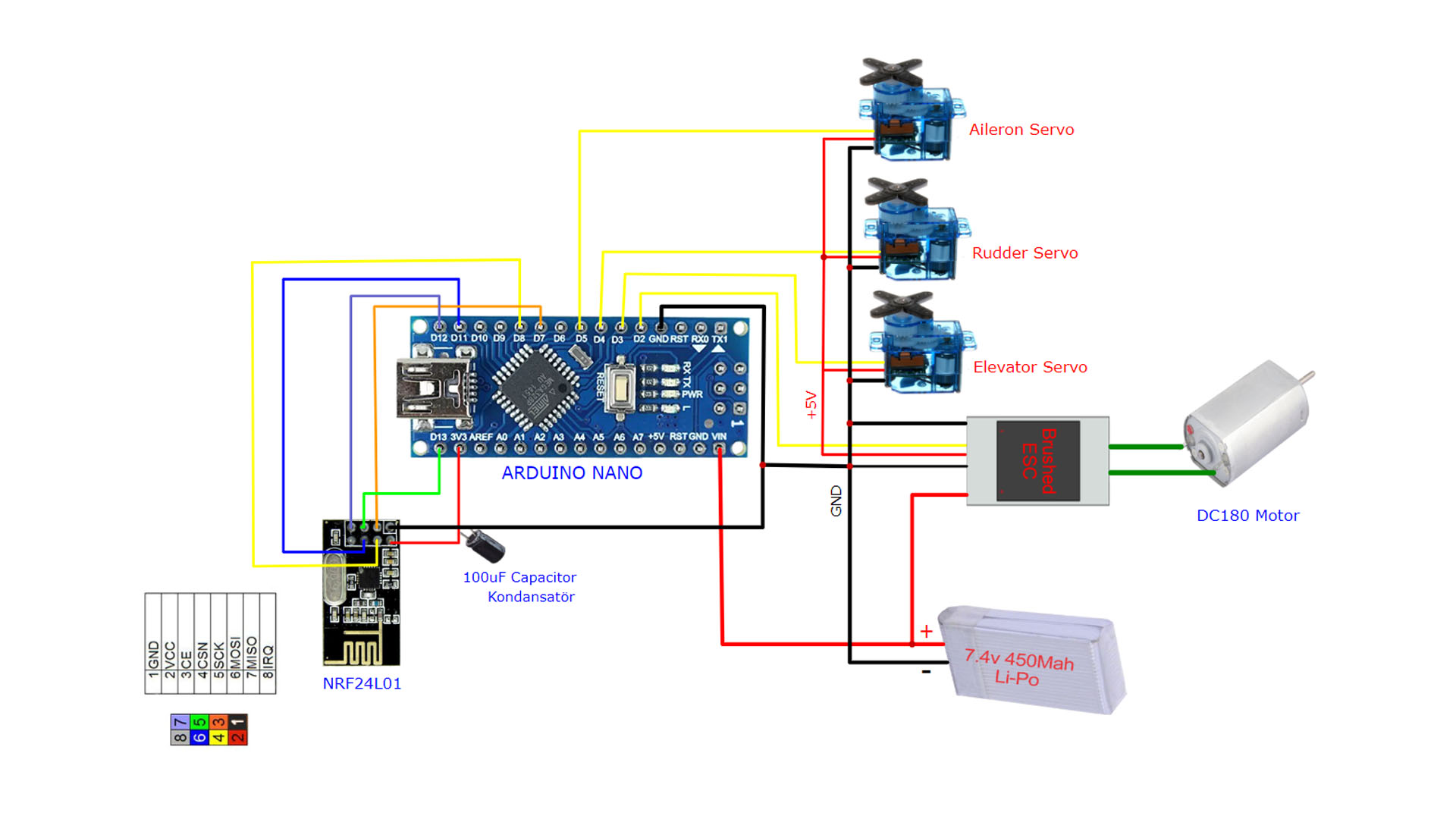
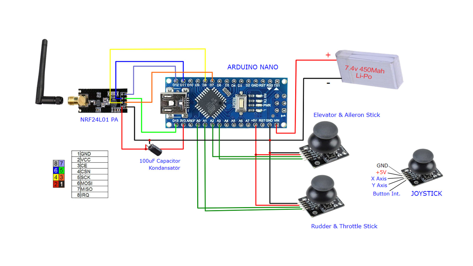
The difference I made was use a LM7805 regulator to get the 7.4v from the 2s battery down to 5v and feed it to an Ams1117 3.3v and power the transmitter from there
As for the receiver, I have disabled autoack, so it can't draw more than 27mA according to the datasheet, or maybe it can? And that could be the issue? I'm driving it directly from the 3.3v pins on the nano
Btw, the NRF24L01 clones I'm using are from Ebyte
E01 2g4m27d

The NRF24 devices are kind of notorious for power supply issues. You can't drive these modules at full power using the Nano as the power supply. They utilize power in a very 'spikey' way so capacitors connected to the GND-VCC pins of the radios are recommended (10-100uF). Also depending on whether or not your devices already have it, adding shielding to the radios can help quite a bit as well. Then make sure your power supply is adequate.

We have a helpful doc: RF24/COMMON_ISSUES.md at master · nRF24/RF24 · GitHub

2 Likes

Hi, @beginner099

Keep the antenna connected as the transmitter needs to see it as a load, leaving the connection open may damage the transmitter.

Tom... :smiley: :+1: :coffee: :australia:

2 Likes

I have added a 100uf capacitor directly to the power pins of the receiver, I realized adding the cap to the transmitter somehow affects it negatively
Could it be that I have to use a more powerful voltage regulator?

Thank you, I just give the webpage you sent me a quick glance and figured out it was exactly my case, I'm powering a 500mW receiver from the very low power output of the nano and the regulator on the transmitter side tends to get really hot when I set pa level to high or max
So it is definitely a power issue
Since I'm using ams1117 3.3v which is rated for 1A max current output, I'm thinking about getting a new voltage regulator that is rated for 3amps, I'll get two of them for both sides, just to be safe, I'm powering the transmitter from two 18650 3.7v batteries, which all that, there shouldn't be a power issue... Just one more thing, I realized the two joystick modules I'm using have a lot of dead zones which makes for a very inaccurate control, can I replace them with two original ps4 thumb sticks? They cost about 2 dollars each, Will that really affect accuracy?

I don't know a lot about voltage regulators, there are others here who can hopefully advise, but it is most likely a power supply issue.

Until that is figured out, you can also try different PA levels and control the LNA by calling radio.setPALevel(RF24_PA_HIGH,0); etc with the 0 disabling the LNA, 1 to enable.

Sorry for throwing lots of questions here, I've been really investing in lots of pcbs and designs and this is the first time I can get an rf design to actually work! I just realized that the ESC starts to run the motor when the joystick is on the middle point and as I push it forward it gradually lowers the rpm of the bldc motor until it is shut off, it's behaving in the reverse way, it has to turn on when I push the joystick forward, how can I change the code to fix that?

Thanks for the replay

Can anyone answer this please

If your transmitter is set to the highest power mode and the receiver is close by - maybe on the same table - then the RF power output from the transmitter will be too much for the receiver to cope with and you will get corrupted or no data.

As you have discovered, reducing the power level allows your setup to work when the transmitter and receiver are close to each other. But, a lower transmitter power will imply a lower operating range.

I seem to recall that there was a library for the nRF24L01 that included the ability to dynamically change the transmitter power level based on the RSSI value provided by the receiver.

EDIT: Sorry, memory failure! The library I was thinking of was for the RFM69 radio module, not the nRF24L01.

1 Like

thank you, can you help me with the code too? The question I asked above about the backward throttle

You should start by putting some debugging print statements in your code for both the Tx and the Rx to see what values are being passed to the ESC. What does your ESC documentation say about the signal applied to it?

1 Like

Okay so today I replaced the old voltage regulator and replaced it with a 5A regulator, it's a AZ1084 3.3v in a to220 package
And the problem is still there, when I change the pa level to high or max, both the regulator and the NRF24L01 get really hot, and it'll only work when I touch the pcb or the antenna... It works just fine on low, what could be the problem here? Cause I'm sure it can't be power,I even screwed the regulator to a huge heat sink there's a 10nf and a 100uf cap in parallel to the power pins of the module, and a 10nf and a 10uf cap in parallel with the regulator inputs...I wanna get the max power out of this module and still be able to control it from a short distance, I'm using two 3dbi antennas for both sides... If I'm charging the receiver too much, then why does it work when I touch the antenna?

Because the antenna is part of a tuned circuit and when you touch the antenna it DE TUNES the circuit and means the RF radiation is very much less.
But, you cannot overload a receiver at close range and expect it to work properly.

Thanks for the reply, but why does the module which works properly at low power gets hot are high or max power?

Are you still using the 7805 to regulate the battery voltage down to 5V or are you driving the AZ1084 directly from the battery?

By "really hot" do you mean too hot to touch for over a second or two?

Do you have a meter that you can measure the current to the transmitter when it is in high power mode?

I guess I need to do that, don't know why I couldn't think of it! I will do it next week cause that's as soon as I can, then I'll update the post
And no I've removed the 7805 cause it's only rated for 1 amp applications I guess ,I also have a 3A buck converter laying around but when I put a cap in parallel with it's output it shows 7.9 v which is the voltage it the two batteries

If for some reason the antenna is a really bad match to the transmitter output some of the power that is supposed to be radiated is instead dissipated in the transmitter. A poor match can be the result of a bad connection to the antenna, e.g. the SMA connector is defective or the electrical path is interrupted somewhere (bad solder joint, open PCB trace, etc.) It can also be the result of a bad module design or incorrect parts. It would be very helpful to know what the module current consumption is in high power mode.

1 Like

Here's the user manual/datasheet
E01-2G4M27D_Usermanual_EN_v1.3 (1).pdf (680.7 KB)
I can measure actual numbers next week when I'm home

Okay, do that.