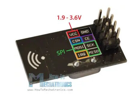
I am using AZDelivery's adapter board to regulate the power input.
These were the results from the test:
CheckConnection Starting

FIRST WITH THE DEFAULT ADDRESSES after power on
  Note that RF24 does NOT reset when Arduino resets - only when power is removed
  If the numbers are mostly 0x00 or 0xff it means that the Arduino is not
     communicating with the nRF24

SPI Speedz	= 10 Mhz
STATUS		= 0xff RX_DR=1 TX_DS=1 MAX_RT=1 RX_P_NO=7 TX_FULL=1
RX_ADDR_P0-1	= 0xffffffff7f 0xffffffffff
RX_ADDR_P2-5	= 0xff 0xff 0xff 0x00
TX_ADDR		= 0x0000000000
RX_PW_P0-6	= 0xff 0xff 0x00 0x7f 0xff 0xff
EN_AA		= 0xff
EN_RXADDR	= 0xff
RF_CH		= 0xff
RF_SETUP	= 0x00
CONFIG		= 0x00
DYNPD/FEATURE	= 0x00 0xff
Data Rate	= 1 MBPS
Model		= nRF24L01+
CRC Length	= 16 bits
PA Power	= PA_MAX
ARC		= 15

AND NOW WITH ADDRESS AAAxR  0x41 41 41 78 52   ON P1
 and 250KBPS data rate

SPI Speedz	= 10 Mhz
STATUS		= 0xff RX_DR=1 TX_DS=1 MAX_RT=1 RX_P_NO=7 TX_FULL=1
RX_ADDR_P0-1	= 0xffffffffff 0xffffffffff
RX_ADDR_P2-5	= 0x00 0xff 0xff 0xff
TX_ADDR		= 0xffffffffff
RX_PW_P0-6	= 0x00 0xff 0xff 0xff 0x00 0xff
EN_AA		= 0x00
EN_RXADDR	= 0x00
RF_CH		= 0xff
RF_SETUP	= 0xff
CONFIG		= 0xff
DYNPD/FEATURE	= 0xff 0x00
Data Rate	= 1 MBPS
Model		= nRF24L01+
CRC Length	= 16 bits
PA Power	= PA_MAX
ARC		= 15
I am unsure of what the next steps are for troubleshooting.
Step1: post an annotated schematic showing exactly how you have wired it. Be sure to note any leads over 10"25cm and how you and all power sources. Also post links to technical information on any other piece of hardware connected to the Arduino.
Step2: We will respond to your schematic.
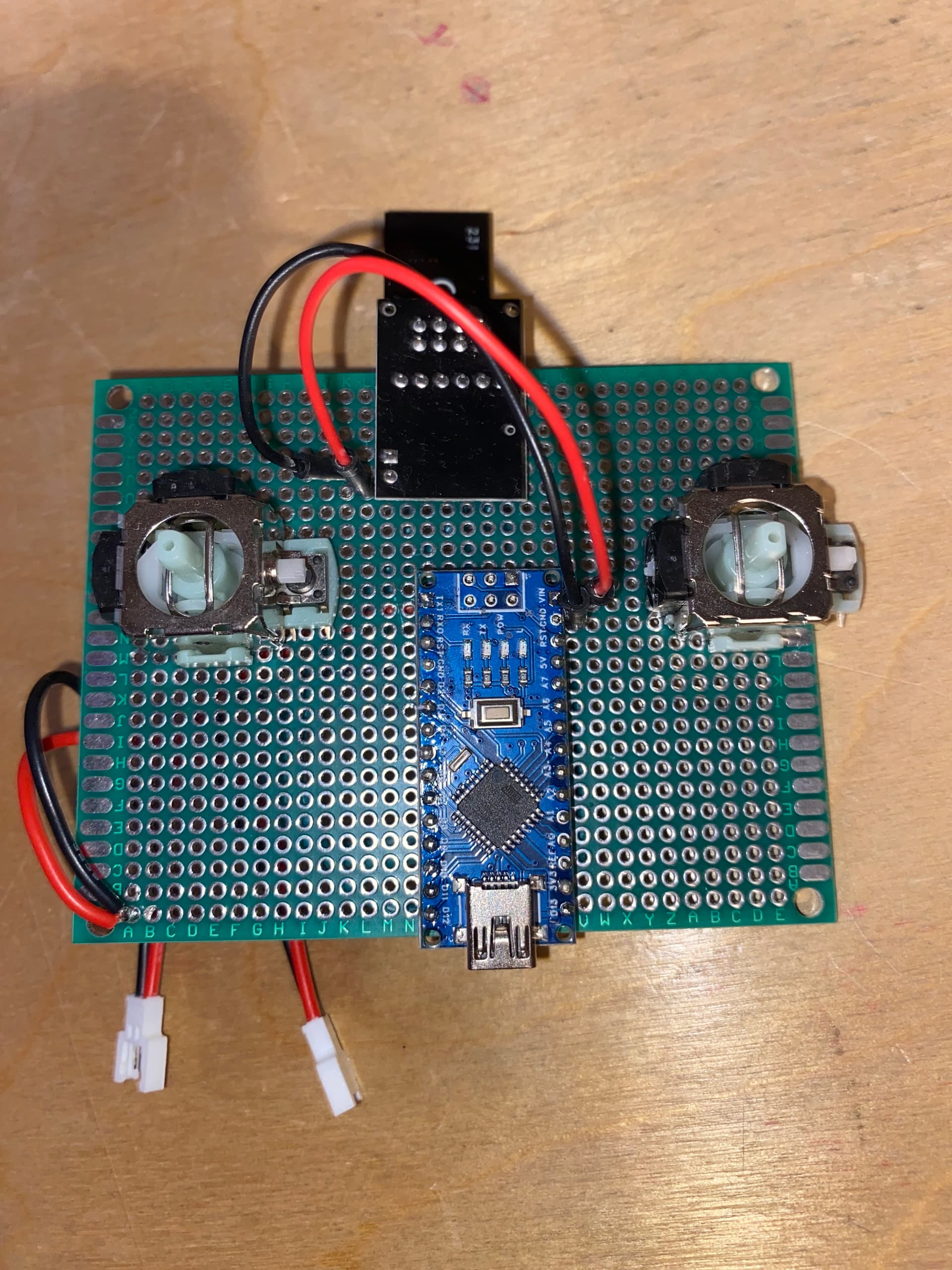
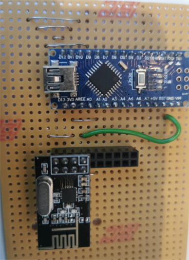
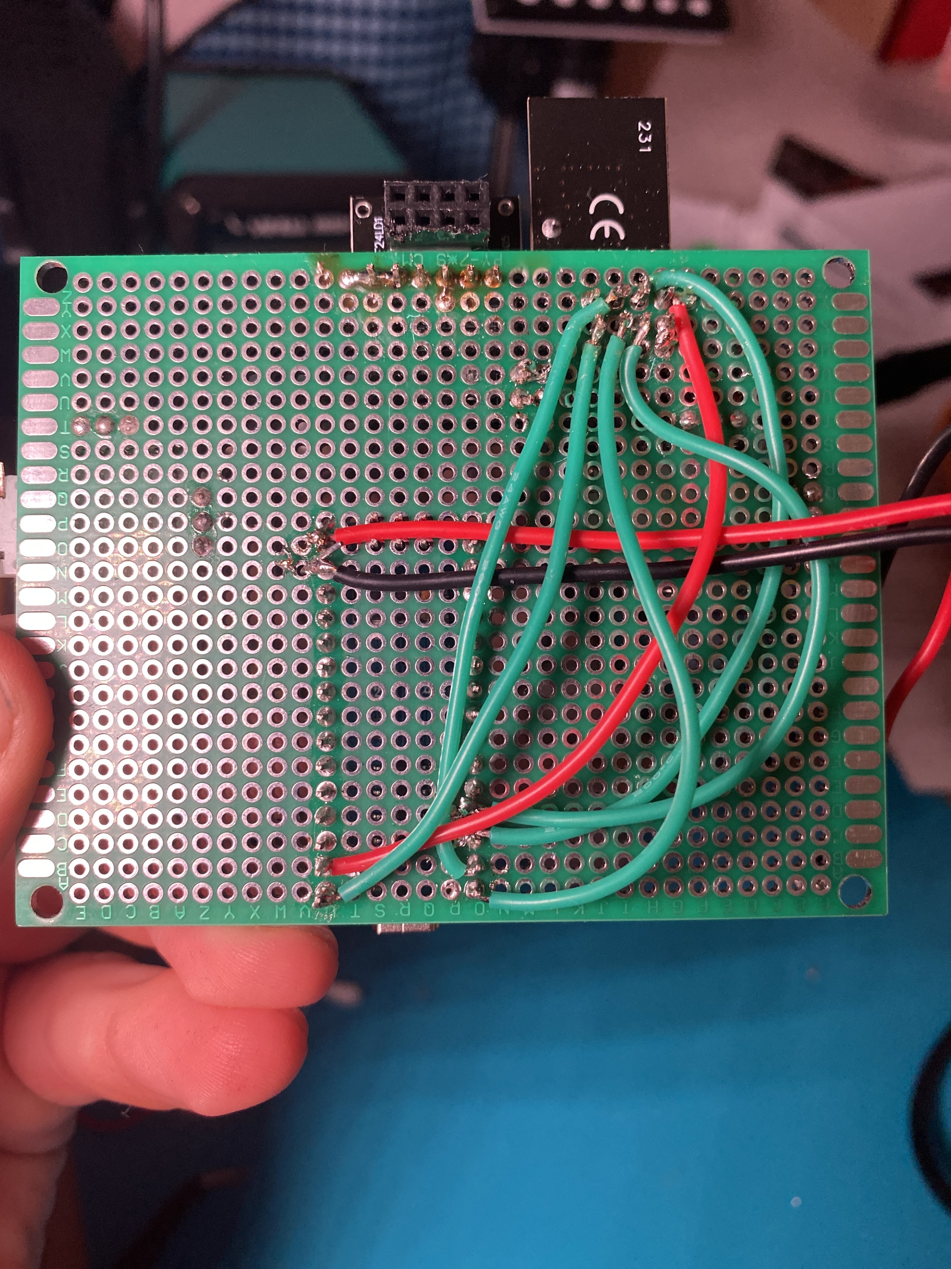
My circuit is based off this schematic, the joysticks are not currently connected. The transciever connections are passed throught an nrf adapter board hence the 7.4V input.
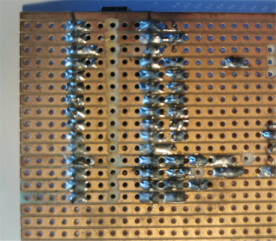
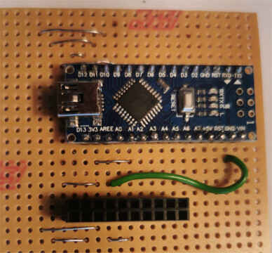
looking at the second photo in post 2 which shows the soldering some of the connections look very doubtful
have you checked the connections with a multimeter for continuity and short circuits?
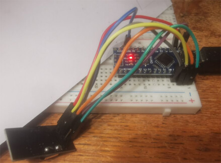
for initial prototyping I tend to use solderless breadboards with Dupont jumper wires - not suitable for long term testing as one can have problems with poor connections
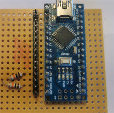
for soldered prototypes I use PCB stripboard, e.g. using a Nano
with tracks close together and cutting tracks between adjacent pins it is easy when soldering to short circuit tracks, etc - testing for continuity and short circuits using a multi-meter is essential
Sorry for the delay in responding. I brought the NRF modules into college today where I could test them with multiple microcontrollers and using breadboards. The connections were tested with a multimeter to ensure correct connections. Unfortunately, after testing and with help from others, the modules are still not producing results.
what code were you using?
how did you connect and power the modules?
on the serial monitor did you get the Transmitter NF24 connected to SPI or the NF24 is NOT connected to SPI message?
anything else on serial monitor?
share a photo?
I was using the code you had sent in previously and the Robin2's CheckConnection.ino
Originally I was using 2 3.7V Lipo batteries in series which I measured having a 7.3V output. These were connected to the nano's Vin pin. But today I was testing using the power input via the USB port.
Nano > NRF24L01 Receive text
NF24 is NOT connected to SPI
and
FIRST WITH THE DEFAULT ADDRESSES after power on
Note that RF24 does NOT reset when Arduino resets - only when power is removed
If the numbers are mostly 0x00 or 0xff it means that the Arduino is not
communicating with the nRF24
SPI Speedz = 10 Mhz
STATUS = 0x00 RX_DR=0 TX_DS=0 MAX_RT=0 RX_P_NO=0 TX_FULL=0
RX_ADDR_P0-1 = 0x0000000000 0xffffffffff
RX_ADDR_P2-5 = 0x00 0xff 0xff 0x00
TX_ADDR = 0x0000000000
RX_PW_P0-6 = 0x00 0xff 0x00 0x00 0xff 0xff
EN_AA = 0xff
EN_RXADDR = 0x00
RF_CH = 0x00
RF_SETUP = 0x00
CONFIG = 0x00
DYNPD/FEATURE = 0x00 0x00
Data Rate = 1 MBPS
Model = nRF24L01+
CRC Length = 16 bits
PA Power = PA_MIN
ARC = 15
AND NOW WITH ADDRESS AAAxR 0x41 41 41 78 52 ON P1
and 250KBPS data rate
SPI Speedz = 10 Mhz
STATUS = 0xff RX_DR=1 TX_DS=1 MAX_RT=1 RX_P_NO=7 TX_FULL=1
RX_ADDR_P0-1 = 0xffffffffff 0xffffffffff
RX_ADDR_P2-5 = 0x00 0x00 0xff 0xff
TX_ADDR = 0xffffffffff
RX_PW_P0-6 = 0x00 0x00 0xff 0xff 0x00 0x00
EN_AA = 0x00
EN_RXADDR = 0x00
RF_CH = 0xff
RF_SETUP = 0xff
CONFIG = 0xff
DYNPD/FEATURE = 0xff 0x00
Data Rate = 1 MBPS
Model = nRF24L01+
CRC Length = Disabled
PA Power = PA_MAX
ARC = 15
The serial monitor did not display anything else.
I never ended up taking a photo of the setup and do not have it with me currently. I could recreate it tomorrow.
The tests today I used the power from the USB port. Previously I was using 2 3.7V lipo batteries in series connected to the nano's Vin port. This was measured at 7.3V.
I have the Vcc pin on the NRF connected to the 3V3 pin on the nano, and have a 10uF capacitor between Vcc and GND.
As described in the RF24 Common Issues Guide, radio modules, especially the PA+LNA versions, are highly reliant on a stable power source. The 3.3V output from Arduino is not stable enough for these modules in many applications. While they may work with an inadequate power supply, you may experience lost packets or reduced reception compared to modules powered by a more stable source.
Symptoms of Power Issues:
Radio module performance may improve when touched, indicating power stability issues.
These issues are often caused by the absence of a capacitor, a common cost-saving omission by some manufacturers.
Temporary Patch:
Add Capacitors: Place capacitors close to the VCC and GND pins of the radio module. A 10uF capacitor is usually sufficient, but the exact value can depend on your circuit layout.
Use Low ESR Capacitors: Capacitors with low Equivalent Series Resistance (ESR) are recommended, as they provide better power stability and performance.
Adding the appropriate capacitors can greatly improve the reliability of your RF24 module by ensuring a stable power supply, thus minimizing packet loss and enhancing overall performance. A separate power supply for the radios is the best solution.
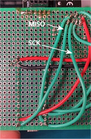
Yeah you're right I had the MISO and SCK mixed up in my example. I swapped them around, tested the NRF with a 3.7V exteral battery and managed to get hold of a 10uF capacitor. I am still recieving the same results.
Nano > NRF24L01 Receive text
NF24 is NOT connected to SPI