nRF24L01+ is communicating with Arduino but not other nRF24L01+

I am at my wits end. I've been trying to get this to work for over a week, I've read every tutorial and forum post I can find and nothing that's been suggested has worked. I apologize in advance if I post something improperly, this is my first post and if something needs to be posted differently please tell me.

I can't get the Simple one way transmission to work from "Simple nRF24L01+ 2.4GHz transceiver demo". I have the nrf24L01+ transceivers hooked up to Nanos. The Nanos are being powered via USB from my computer and the nrf24L01s are being powered from independent 3.3V voltage regulators which are being powered from a separate USB cable also hooked up to my computer. There are 10uF capacitors from 3.3V to ground on the outputs of the voltage regulators. I've checked out all of the connections with my multimeter (and measured all of the voltages) and everything is going where it's supposed to be going and getting the voltage it's supposed to be getting. I've also tried several different nRF24L01s on both the transmitting and receiving sides and I even tried different Nanos, wires, cables, capacitors, and voltage regulators. Here's a picture (the USB cable for the Nano isn't in the picture but that's how the Nanos are being powered):

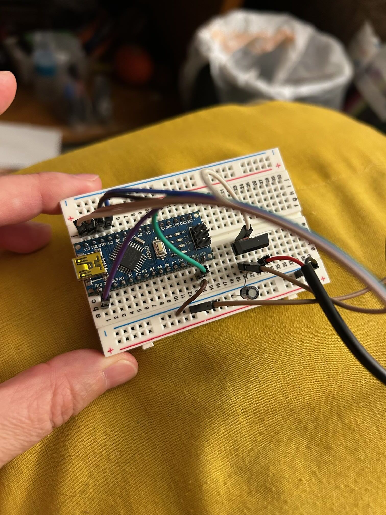
I have version 1.1.7 of RF24 by TMRh20 installed

I uploaded the following code:

Receiver:

// SimpleRx - the slave or the receiver

#include <SPI.h>
#include <nRF24L01.h>
#include <RF24.h>

#define CE_PIN   9
#define CSN_PIN 10

const byte thisSlaveAddress[5] = {'R','x','A','A','A'};

RF24 radio(CE_PIN, CSN_PIN);

char dataReceived[10]; // this must match dataToSend in the TX
bool newData = false;

//===========

void setup() {

    Serial.begin(9600);

    Serial.println("SimpleRx Starting");
    radio.begin();
    radio.setDataRate( RF24_250KBPS );
    radio.openReadingPipe(1, thisSlaveAddress);
    radio.startListening();
}

//=============

void loop() {
    getData();
    showData();
}

//==============

void getData() {
    if ( radio.available() ) {
        radio.read( &dataReceived, sizeof(dataReceived) );
        newData = true;
    }
}

void showData() {
    if (newData == true) {
        Serial.print("Data received ");
        Serial.println(dataReceived);
        newData = false;
    }
}

Transmitter:

// SimpleTx - the master or the transmitter

#include <SPI.h>
#include <nRF24L01.h>
#include <RF24.h>


#define CE_PIN   9
#define CSN_PIN 10

const byte slaveAddress[5] = {'R','x','A','A','A'};


RF24 radio(CE_PIN, CSN_PIN); // Create a Radio

char dataToSend[10] = "Message 0";
char txNum = '0';


unsigned long currentMillis;
unsigned long prevMillis;
unsigned long txIntervalMillis = 1000; // send once per second


void setup() {

    Serial.begin(9600);

    Serial.println("SimpleTx Starting");

    radio.begin();
    radio.setDataRate( RF24_250KBPS );
    radio.setRetries(3,5); // delay, count
    radio.openWritingPipe(slaveAddress);
}

//====================

void loop() {
    currentMillis = millis();
    if (currentMillis - prevMillis >= txIntervalMillis) {
        send();
        prevMillis = millis();
    }
}

//====================

void send() {

    bool rslt;
    rslt = radio.write( &dataToSend, sizeof(dataToSend) );
        // Always use sizeof() as it gives the size as the number of bytes.
        // For example if dataToSend was an int sizeof() would correctly return 2

    Serial.print("Data Sent ");
    Serial.print(dataToSend);
    if (rslt) {
        Serial.println("  Acknowledge received");
        updateMessage();
    }
    else {
        Serial.println("  Tx failed");
    }
}

//================

void updateMessage() {
        // so you can see that new data is being sent
    txNum += 1;
    if (txNum > '9') {
        txNum = '0';
    }
    dataToSend[8] = txNum;
}

In the serial monitor the transmitter keeps spitting out "Data Sent Message 0 Tx failed" repeatedly and the receiver just sits at "SimpleRx Starting". I uploaded the following code to see if the nRF24L01s were connecting to the Nanos:

// 18 Mar 2018 - simple program to verify connection between Arduino
//      and nRF24L01+
//  This program does NOT attempt any communication with another nRF24

#include <SPI.h>
#include <nRF24L01.h>
#include <RF24.h>

#include <printf.h>

#define CE_PIN   9
#define CSN_PIN 10

const byte thisSlaveAddress[5] = {'R','x','A','A','A'};

RF24 radio(CE_PIN, CSN_PIN);

char dataReceived[10]; // this must match dataToSend in the TX
bool newData = false;


void setup() {
    Serial.begin(9600);
    printf_begin();

    Serial.println("CheckConnection Starting");
    Serial.println();
    Serial.println("FIRST WITH THE DEFAULT ADDRESSES after power on");
    Serial.println("  Note that RF24 does NOT reset when Arduino resets - only when power is removed");
    Serial.println("  If the numbers are mostly 0x00 or 0xff it means that the Arduino is not");
    Serial.println("     communicating with the nRF24");
    Serial.println();
    radio.begin();
    radio.printDetails();
    Serial.println();
    Serial.println();
    Serial.println("AND NOW WITH ADDRESS AAAxR  0x41 41 41 78 52   ON P1");
    Serial.println(" and 250KBPS data rate");
    Serial.println();
    radio.openReadingPipe(1, thisSlaveAddress);
    radio.setDataRate( RF24_250KBPS );
    radio.printDetails();
    Serial.println();
    Serial.println();
}


void loop() {

}

Here's what I got for the receiver:

FIRST WITH THE DEFAULT ADDRESSES after power on
Note that RF24 does NOT reset when Arduino resets - only when power is removed
If the numbers are mostly 0x00 or 0xff it means that the Arduino is not
communicating with the nRF24

STATUS = 0x0e RX_DR=0 TX_DS=0 MAX_RT=0 RX_P_NO=7 TX_FULL=0
RX_ADDR_P0-1 = 0xe7e7e7e7e7 0x4141417852
RX_ADDR_P2-5 = 0xc3 0xc4 0xc5 0xc6
TX_ADDR = 0xe7e7e7e7e7
RX_PW_P0-6 = 0x00 0x20 0x00 0x00 0x00 0x00
EN_AA = 0x3f
EN_RXADDR = 0x03
RF_CH = 0x4c
RF_SETUP = 0x07
CONFIG = 0x0e
DYNPD/FEATURE = 0x00 0x00
Data Rate = 1MBPS
Model = nRF24L01+
CRC Length = 16 bits
PA Power = PA_MAX

AND NOW WITH ADDRESS AAAxR 0x41 41 41 78 52 ON P1
and 250KBPS data rate

STATUS = 0x0e RX_DR=0 TX_DS=0 MAX_RT=0 RX_P_NO=7 TX_FULL=0
RX_ADDR_P0-1 = 0xe7e7e7e7e7 0x4141417852
RX_ADDR_P2-5 = 0xc3 0xc4 0xc5 0xc6
TX_ADDR = 0xe7e7e7e7e7
RX_PW_P0-6 = 0x00 0x20 0x00 0x00 0x00 0x00
EN_AA = 0x3f
EN_RXADDR = 0x03
RF_CH = 0x4c
RF_SETUP = 0x27
CONFIG = 0x0e
DYNPD/FEATURE = 0x00 0x00
Data Rate = 250KBPS
Model = nRF24L01+
CRC Length = 16 bits
PA Power = PA_MAX

And here's what I got for the transmitter:

FIRST WITH THE DEFAULT ADDRESSES after power on
Note that RF24 does NOT reset when Arduino resets - only when power is removed
If the numbers are mostly 0x00 or 0xff it means that the Arduino is not
communicating with the nRF24

STATUS = 0x0e RX_DR=0 TX_DS=0 MAX_RT=0 RX_P_NO=7 TX_FULL=0
RX_ADDR_P0-1 = 0xe7e7e7e7e7 0x4141417852
RX_ADDR_P2-5 = 0xc3 0xc4 0xc5 0xc6
TX_ADDR = 0xe7e7e7e7e7
RX_PW_P0-6 = 0x00 0x20 0x00 0x00 0x00 0x00
EN_AA = 0x3f
EN_RXADDR = 0x03
RF_CH = 0x4c
RF_SETUP = 0x07
CONFIG = 0x0e
DYNPD/FEATURE = 0x00 0x00
Data Rate = 1MBPS
Model = nRF24L01+
CRC Length = 16 bits
PA Power = PA_MAX

AND NOW WITH ADDRESS AAAxR 0x41 41 41 78 52 ON P1
and 250KBPS data rate

STATUS = 0x0e RX_DR=0 TX_DS=0 MAX_RT=0 RX_P_NO=7 TX_FULL=0
RX_ADDR_P0-1 = 0xe7e7e7e7e7 0x4141417852
RX_ADDR_P2-5 = 0xc3 0xc4 0xc5 0xc6
TX_ADDR = 0xe7e7e7e7e7
RX_PW_P0-6 = 0x00 0x20 0x00 0x00 0x00 0x00
EN_AA = 0x3f
EN_RXADDR = 0x03
RF_CH = 0x4c
RF_SETUP = 0x27
CONFIG = 0x0e
DYNPD/FEATURE = 0x00 0x00
Data Rate = 250KBPS
Model = nRF24L01+
CRC Length = 16 bits
PA Power = PA_MAX

From what I understand both of the nRFs are connecting to their Nanos. I've run out of things to try and would appreciate any help or suggestions.

Download the scanner program for starters to make sure that both modules work on the reception

/*
 * Copyright (C) 2011 J. Coliz <maniacbug@ymail.com>
 * Updated 2020 TMRh20
 *
 * This program is free software; you can redistribute it and/or
 * modify it under the terms of the GNU General Public License
 * version 2 as published by the Free Software Foundation.
 */

/**
 * Channel scanner and Continuous Carrier Wave Output
 *
 * Example to detect interference on the various channels available.
 * This is a good diagnostic tool to check whether you're picking a
 * good channel for your application.
 *
 * Run this sketch on two devices. On one device, start CCW output by sending a 'g'
 * character over Serial. The other device scanning should detect the output of the sending
 * device on the given channel. Adjust channel and output power of CCW below.
 *
 * Inspired by cpixip.
 * See http://arduino.cc/forum/index.php/topic,54795.0.html
 */

#include "RF24.h"
#include "printf.h"

//
// Hardware configuration
//

// Set up nRF24L01 radio on SPI bus plus pins 7 & 8

RF24 radio(7, 8);

//
// Channel info
//

const uint8_t num_channels = 126;
uint8_t values[num_channels];

//
// Setup
//

void setup(void) {
  //
  // Print preamble
  //

  Serial.begin(115200);
  printf_begin();
  Serial.println(F("\n\rRF24/examples/scanner/"));

  //
  // Setup and configure rf radio
  //

  radio.begin();
  radio.setAutoAck(false);

  // Get into standby mode
  radio.startListening();
  radio.stopListening();
  radio.printDetails();

  //delay(1000);
  // Print out header, high then low digit
  int i = 0;
  while (i < num_channels) {
    Serial.print(i >> 4, HEX);
    ++i;
  }
  Serial.println();
  i = 0;
  while (i < num_channels) {
    Serial.print(i & 0xf, HEX);
    ++i;
  }
  Serial.println();
  //delay(1000);
}

//
// Loop
//

const int num_reps = 100;
bool constCarrierMode = 0;

void loop(void) {
  /****************************************/
  // Send g over Serial to begin CCW output
  // Configure the channel and power level below
  if (Serial.available()) {
    char c = Serial.read();
    if (c == 'g') {
      constCarrierMode = 1;
      radio.stopListening();
      delay(2);
      Serial.println("Starting Carrier Out");
      radio.startConstCarrier(RF24_PA_LOW, 40);
    } else if (c == 'e') {
      constCarrierMode = 0;
      radio.stopConstCarrier();
      Serial.println("Stopping Carrier Out");
    }
  }
  /****************************************/

  if (constCarrierMode == 0) {
    // Clear measurement values
    memset(values, 0, sizeof(values));

    // Scan all channels num_reps times
    int rep_counter = num_reps;
    while (rep_counter--) {
      int i = num_channels;
      while (i--) {
        // Select this channel
        radio.setChannel(i);

        // Listen for a little
        radio.startListening();
        delayMicroseconds(128);
        radio.stopListening();

        // Did we get a carrier?
        if (radio.testCarrier()) {
          ++values[i];
        }
      }
    }


    // Print out channel measurements, clamped to a single hex digit
    int i = 0;
    while (i < num_channels) {
      if (values[i])
        Serial.print(min(0xf, values[i]), HEX);
      else
        Serial.print(F("-"));

      ++i;
    }
    Serial.println();

  }  //If constCarrierMode == 0
}

The A Nano cannot properly supply power to the radio, it is sometimes maby.

Power Stability Issues with RF24 Radio Modules

As described in the RF24 Common Issues Guide, radio modules, especially the PA+LNA versions, are highly reliant on a stable power source. The 3.3V output from Arduino is not stable enough for these modules in many applications. While they may work with an inadequate power supply, you may experience lost packets or reduced reception compared to modules powered by a more stable source. The Nano/UNO 5V is also a problem, it has problems supplying enough current during transmit.

Symptoms of Power Issues:

  • Radio module performance may improve when touched, indicating power stability issues.

  • These issues are often caused by the absence of a capacitor, a common cost-saving omission by some manufacturers.

Temporary Patch:

  • Add Capacitors: Place capacitors close to the VCC and GND pins of the radio module. A 10uF capacitor is usually sufficient, but the exact value can depend on your circuit layout.

  • Use Low ESR Capacitors: Capacitors with low Equivalent Series Resistance (ESR) are recommended, as they provide better power stability and performance.

  • Be sure the transmitter and receiver are at least a meter apart, more is better.

  • RF24/COMMON_ISSUES.md at master · nRF24/RF24 · GitHub

Adding the appropriate capacitors can greatly improve the reliability of your RF24 module by ensuring a stable power supply, thus minimizing packet loss and enhancing overall performance. A separate power supply for the radios is the best solution.

Hopefully this helps.

It does sound like it is related to power.

Some Nanos, including the official Arduino Nano R3, derive the 3v3 from the USB chip and this provides a maximum of about 50mA, and that only when the USB cable is connected, which is insufficient for the NRF24L01 devices. Other Nano clones have a dedicated 3v3 voltage regulator and can supply more current. From the pictures you have shown, it is not clear which type of Nano you are using. The voltage regulators are usually on the underside of the board.

Two AA cells are usually a good way to ensure that the NRF24L01 is getting sufficient power. Also there are dedicated adapter boards for NRF24l01 devices which include a voltage regulator and capacitors.

Ensure that any separate power source has a common ground also with the Nano.

Hi, @redteamgo
Welcome to the forum.

Thanks for the informative first post. :+1: :+1:

Can you please post a copy of your circuit, a picture of a hand drawn circuit in jpg, png?
Hand drawn and photographed is perfectly acceptable.
Please include ALL hardware, power supplies, component names and pin labels.

Note that even your designated "receiver" still transmits, so its power supply has to be as robust as your designated "transmitter".

Tom.... :smiley: :+1: :coffee: :australia:

Another problem is that if the nRF24L01 modules are too close to each other they can overload. I have found they work better if they are more than ~6 feet apart.

I'm not sure how to use this, can you provide a little bit more information or point me to where there are more specific instructions. Thanks

I have them sitting about 8 feet apart

I'm working on drawing the circuit right now. The receiver and the transmitter are hooked up exactly the same.

Just upload this sketch, the serial monitor will display the scanning process of the frequency range of this module

It says to run it on two devices, I can't figure out how they're supposed to talk to each other if the exact same sketch is on both.

I'm using an external power supply (not the Nano 3.3V) with a low ESR cap across VCC and GND.

I'm already using a separate power source and it's ground is connected to the Nano's ground

Hi, @redteamgo
Not that it matters in this case;

???

I thought this was a plus model.

Have you spaced them like @gilshultz has suggested?

Tom.... :smiley: :+1: :coffee: :australia:

First, you need to make sure both modules are working, at least for reception; everything is written in the sketch text. Why this sketch!

The one you have shown is a nRF24L01+PA+LNA, the one I'm using is just a nRF24L01+ and yes I have them spaced around 8 feet apart

I uploaded the sketch and the serial monitor just spits out garbage

Hello redteamgo

Take a view here to get some additional information.

wbr Paul

update your photos to show the external power supplies, the adapter boards appear to be powered from the Nano 5V

Hi, @redteamgo

Have you go the baud rate of the IDE serial monitor set for the same speed as in the code?

Tom.... :smiley: :+1: :coffee: :australia: