Hello,
I've been trying to get my NRF24L01+PA+LNA up and running for a few days now, but unfortunately it's not working. I already had it running once, but then tried to convert it from an arduino uno to an ELEGOO Mega2560 R3 and since then it doesn't work anymore. Also tried to build it back to the Arduino Uno but that doesn't work anymore either.
I would be very happy about help.
Thanks for the help.
I looked at it again and swapped the PINS.
I also read through the tutorial, but there I could not conclude anything new from it either.
Yes, my CE pins are both on PIN7 and CSN on PIN8. I use the 5V from the Arduino itself because I use the "Breadboard Breakout Adapter" and I read that it needs 5V.
In Robin2's tutorial in reply #30 is the check connection test code. That code provides a way to test the electrical connection between the rf24 module and its attached processor (not wireless connection). It may be worth running the code on your Nano and Mega to check the physical connections.
FIRST WITH THE DEFAULT ADDRESSES after power on
  Note that RF24 does NOT reset when Arduino resets - only when power is removed
  If the numbers are mostly 0x00 or 0xff it means that the Arduino is not
     communicating with the nRF24

SPI Speedz	= 10 Mhz
STATUS		= 0x0e RX_DR=0 TX_DS=0 MAX_RT=0 RX_P_NO=7 TX_FULL=0
RX_ADDR_P0-1	= 0xe7e7e7e7e7 0x4141417852
RX_ADDR_P2-5	= 0xc3 0xc4 0xc5 0xc6
TX_ADDR		= 0xe7e7e7e7e7
RX_PW_P0-6	= 0x20 0x20 0x20 0x20 0x20 0x20
EN_AA		= 0x3f
EN_RXADDR	= 0x03
RF_CH		= 0x4c
RF_SETUP	= 0x07
CONFIG		= 0x0e
DYNPD/FEATURE	= 0x00 0x00
Data Rate	= 1 MBPS
Model		= nRF24L01+
CRC Length	= 16 bits
PA Power	= PA_MAX
ARC		= 0


AND NOW WITH ADDRESS AAAxR  0x41 41 41 78 52   ON P1
 and 250KBPS data rate

SPI Speedz	= 10 Mhz
STATUS		= 0x0e RX_DR=0 TX_DS=0 MAX_RT=0 RX_P_NO=7 TX_FULL=0
RX_ADDR_P0-1	= 0xe7e7e7e7e7 0x4141417852
RX_ADDR_P2-5	= 0xc3 0xc4 0xc5 0xc6
TX_ADDR		= 0xe7e7e7e7e7
RX_PW_P0-6	= 0x20 0x20 0x20 0x20 0x20 0x20
EN_AA		= 0x3f
EN_RXADDR	= 0x03
RF_CH		= 0x4c
RF_SETUP	= 0x27
CONFIG		= 0x0e
DYNPD/FEATURE	= 0x00 0x00
Data Rate	= 250 KBPS
Model		= nRF24L01+
CRC Length	= 16 bits
PA Power	= PA_MAX
ARC		= 0
Test with Arduino Nano
CheckConnection Starting

FIRST WITH THE DEFAULT ADDRESSES after power on
  Note that RF24 does NOT reset when Arduino resets - only when power is removed
  If the numbers are mostly 0x00 or 0xff it means that the Arduino is not
     communicating with the nRF24


AND NOW WITH ADDRESS AAAxR  0x41 41 41 78 52   ON P1
 and 250KBPS data rate
It looks like the problem is with the Arduino Nano.
I replaced the Arduino nano with an Arduino uno and I got this result. So it looks like the problem is with the Arduino nano.
FIRST WITH THE DEFAULT ADDRESSES after power on
  Note that RF24 does NOT reset when Arduino resets - only when power is removed
  If the numbers are mostly 0x00 or 0xff it means that the Arduino is not
     communicating with the nRF24

SPI Speedz	= 10 Mhz
STATUS		= 0x0e RX_DR=0 TX_DS=0 MAX_RT=0 RX_P_NO=7 TX_FULL=0
RX_ADDR_P0-1	= 0xe7e7e7e7e7 0xc2c2c2c2c2
RX_ADDR_P2-5	= 0xc3 0xc4 0xc5 0xc6
TX_ADDR		= 0xe7e7e7e7e7
RX_PW_P0-6	= 0x20 0x20 0x20 0x20 0x20 0x20
EN_AA		= 0x3f
EN_RXADDR	= 0x03
RF_CH		= 0x4c
RF_SETUP	= 0x07
CONFIG		= 0x0e
DYNPD/FEATURE	= 0x00 0x00
Data Rate	= 1 MBPS
Model		= nRF24L01+
CRC Length	= 16 bits
PA Power	= PA_MAX
ARC		= 0


AND NOW WITH ADDRESS AAAxR  0x41 41 41 78 52   ON P1
 and 250KBPS data rate

SPI Speedz	= 10 Mhz
STATUS		= 0x0e RX_DR=0 TX_DS=0 MAX_RT=0 RX_P_NO=7 TX_FULL=0
RX_ADDR_P0-1	= 0xe7e7e7e7e7 0x4141417852
RX_ADDR_P2-5	= 0xc3 0xc4 0xc5 0xc6
TX_ADDR		= 0xe7e7e7e7e7
RX_PW_P0-6	= 0x20 0x20 0x20 0x20 0x20 0x20
EN_AA		= 0x3f
EN_RXADDR	= 0x03
RF_CH		= 0x4c
RF_SETUP	= 0x27
CONFIG		= 0x0e
DYNPD/FEATURE	= 0x00 0x00
Data Rate	= 250 KBPS
Model		= nRF24L01+
CRC Length	= 16 bits
PA Power	= PA_MAX
ARC		= 0
But I tested my test communication script with the Uno and the Mega and it doesn't work either.
In your original post, you have effectively configured a different data rate between the transmitter and the receiver since the default data rate is 1MBPS.
Find a reliable tutorial, such as the one mentioned in post #8, and copy its code exactly but adapting pin numbers if required.
The NRF24L01 modules such as the ones you are using, with the PA and antenna, can be extremely difficult to set up. I have a project on my desk at the moment with 2 of these and using a new ATTiny series. Soldering a 10uF capacitor directly across the power rails on the module helped most. Unscrewing the antennas and lowering the transmission power to its minimum could also help.
In my case, since I have also the non-PA modules, I was able to rule out a configuration problem quite quickly.
Here is code that I tested on an Uno and a Mega. The code is modified from Robin2's simple RF24 tutorial. The code is compiled using the latest version of the RF24 library (installed from the IDE library manager). The code sends a incrementing integer from transmitter to receiver. I do not have the high power RF24 radio modules, so tested with regular ones.
Pins
Name      rf24        Uno         Mega
gnd       gnd         gnd         gnd
Vcc       Vcc          Vcc          Vcc
CE         3            7            7
CSN        4            8            8
SCK        5           13            52
MOSI       6           11            51
MISO       7           12            50
int        8           NC            NC
Transmitter (Uno):
// SimpleTx - the master or the transmitter

#include <SPI.h>
#include <nRF24L01.h>
#include <RF24.h>


const byte CE_PIN = 7;
const byte CSN_PIN = 8;

const byte slaveAddress[5] = {'R', 'x', 'A', 'A', 'A'};


RF24 radio(CE_PIN, CSN_PIN); // Create a Radio

int dataToSend = 123;

unsigned long currentMillis;
unsigned long prevMillis;
unsigned long txIntervalMillis = 1000; // send once per second

void setup()
{

   Serial.begin(9600);

   Serial.println("SimpleTx Starting");

   radio.begin();
   //RF24_1MBPS, RF24_2MBPS, RF24_250KBPS
   radio.setDataRate( RF24_250KBPS );
   radio.setRetries(3, 5); // delay, count
   //radio.setChannel(10);
   //RF24_PA_MIN = 0,RF24_PA_LOW, RF24_PA_HIGH, RF24_PA_MAX
   radio.setPALevel(RF24_PA_LOW);
   radio.openWritingPipe(slaveAddress);
}

//====================

void loop()
{
   currentMillis = millis();
   if (currentMillis - prevMillis >= txIntervalMillis)
   {
      dataToSend++;
      send();
      prevMillis = millis();
   }
}

//====================

void send()
{
   bool rslt;
   rslt = radio.write( &dataToSend, sizeof(dataToSend) );
   // Always use sizeof() as it gives the size as the number of bytes.
   // For example if dataToSend was an int sizeof() would correctly return 2

   Serial.print("Data Sent ");
   Serial.print(dataToSend);
   if (rslt)
   {
      Serial.println("  Acknowledge received");
   }
   else
   {
      Serial.println("  Tx failed");
   }
}
Thanks again for the help. Unfortunately this does not work either. I tried to recreate it exactly the same way, only I used the high power RF24 radio modules. The transmitter consistently gives "Tx failed". What does this mean/how to fix it?
Do you see anything on the serial console of the receiver ?
The message you got may only mean that the ack failed to get back from the receiver to the transmitter.
Some models of the NRF24L01 don't support 250KBPS.
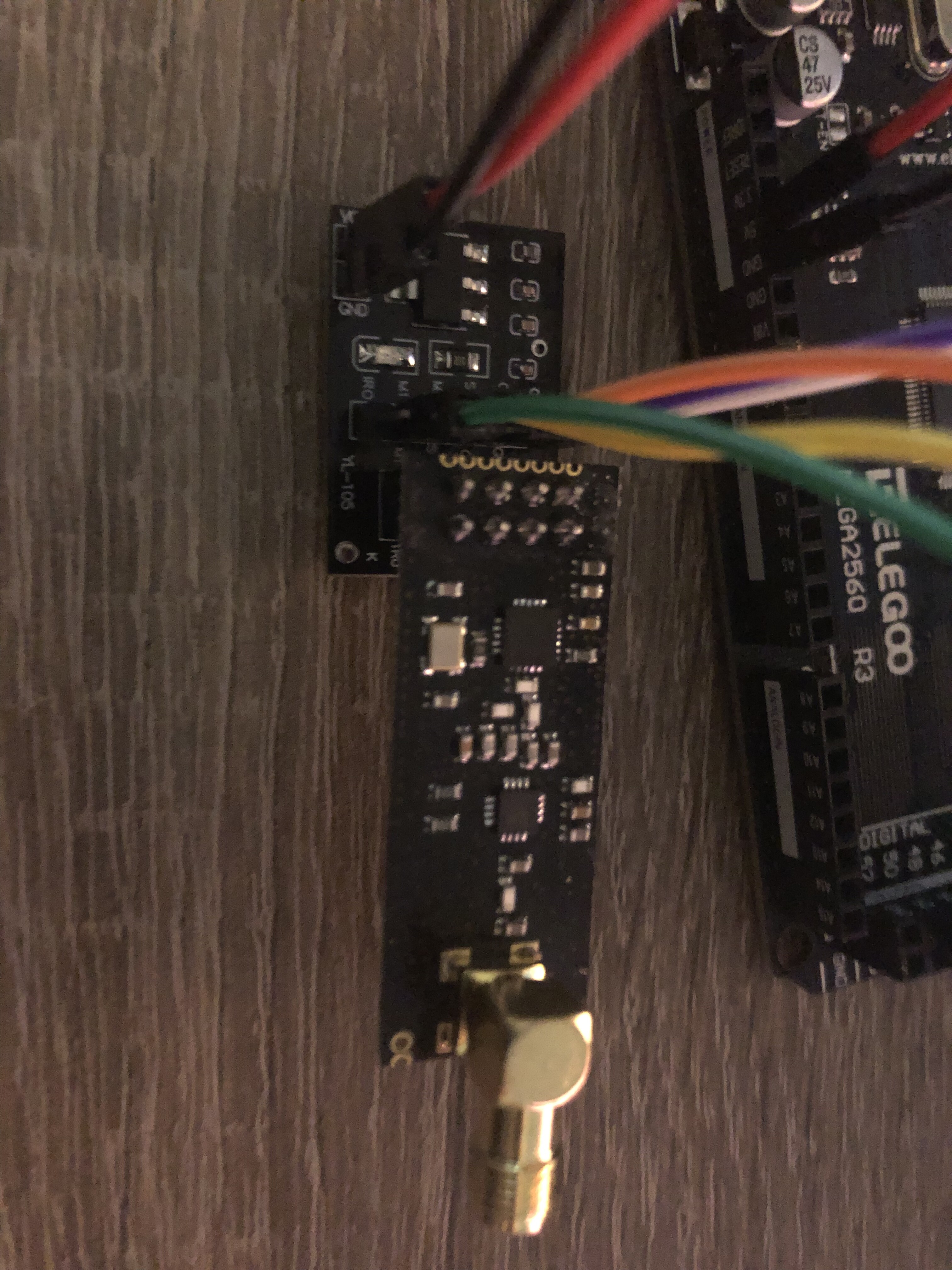
If that still fails, provide a good close up picture of your NRF24L01 modules.
However, then, the most likely cause is a power problem.