I will think about this. Thanks a lot
What is a captor?
No, it is the right thing to do. Bringing your view into production endangers people.
Presenting a COTS toy?
You only need to re-route 4 of your existing wires ( 3v7×2  , servo , and two VCC2); disconnect these 4 wires from the breadboard rail(s), and insert them into a common, previously unoccupied breadboard row. Test everything using a USB connection for Arduino power, and once satisfied that it works, add a separate power source for the Arduino (via the VIN pin or barrel jack).
Alright!
Before actually re-rooting it, what about the Vcc1 of the drivers? (L293D) they re actually headed to + of the breadboard.
That should be connected to the Uno 5V.
Your batteries should be connected to Vin not 5V, as you show in your diagram.
If you disconnect the batteries from the breadboard rail as I have suggested, then the VCC1 pins will be connected to the 5V rail from the Arduino (which is also routed to the breadboard ). This is as it should be.
The pictures show two 3.7V batteries, probably in series and if connected to the 5V output pin that would have fried the Uno long ago. I suspect that it is not wired as shown in post #1
The photos in posts #23 and #24 have the battery leads (red and black) disconnected from the breadboard, so impossible to tell. But it does seem that the Arduino 5V and GND pins have jumper wires (purple and white) that are inserted into the breadboard's lefthand and  rails, respectively.
Everything should stay as is, except for the 4 wires that I mentioned in post #43.
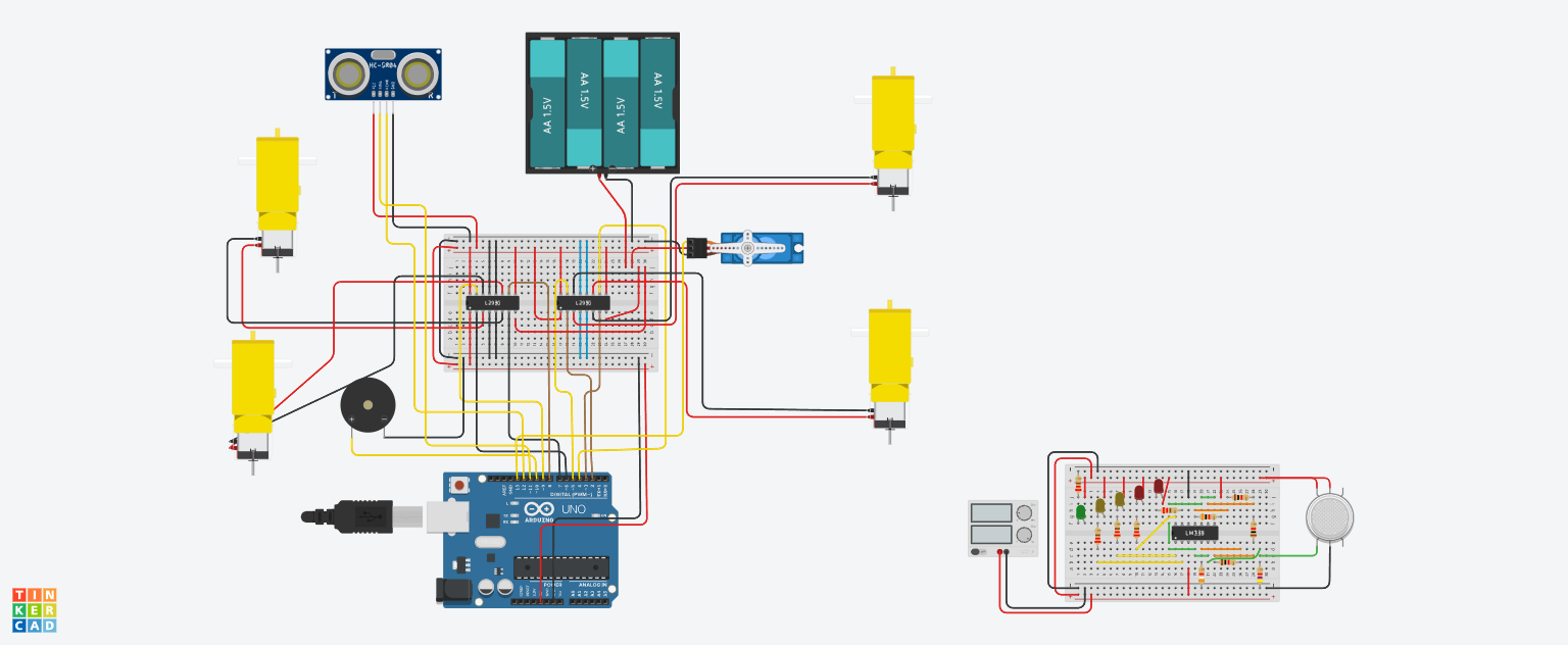
I'm surprised you get any motion at all. You have not connected the 4 wires in the same row, as I had suggested. In your diagram, the breadboard is sideways, so the "rows" are vertical. You have inserted each of the 4 wires into column "j", but in four separate rows (27–30). This means that none of the wires are connected to anything! You must insert them into a single row of the breadboard to make an electrical connection. For example, insert the 4 wires into columns "g", h", "i", and "j" in row 30.
For information about how a solderless breadboard works, please see:
Now Showing: Explaining the L293D


Wow, you created a lot of unnecessary work for yourself if you rotated one of the L293D chips to create this new version!!! Hopefully you did not make any mistakes when you re-routed the 16 wires that were connected to the driver.
In the schematic, the 4 power wires are now adequately connected (and I hope it is the same in your real-life circuit). I have not checked the rest of your schematic after this major revision that you made.
So... does it work now, when the Arduino is powered by USB?
Yes because i found that my L293D were pointed inwards xd, took me a good 35 min to check all the connections again. i m certain it's the same as the one i made!
The wheels seem powered fine but the HC-04 again, rarely detects its obstacles. and a second problem, sometimes looking in the Serial Monitor the HC04 does detect the small distances, makes the necessary action but the servo doesn't rotate left/rotate.
Basically 2 problems!
Using this code :
`#include <Servo.h>

// Broches pour les drivers de moteur L293D (côté gauche et côté droit)
const int IN1_leftRear = 2;   // Driver gauche IN1 (moteur arrière gauche)
const int IN2_leftRear = 3;   // Driver gauche IN2 (moteur arrière gauche)
const int IN3_leftFront = 4;  // Driver gauche IN3 (moteur avant gauche)
const int IN4_leftFront = 5;  // Driver gauche IN4 (moteur avant gauche)

const int IN1_rightRear = 6;  // Driver droit IN3 (moteur arrière droit)
const int IN2_rightRear = 7;  // Driver droit IN4 (moteur arrière droit)
const int IN1_rightFront = 8; // Driver droit IN1 (moteur avant droit)
const int IN2_rightFront = 9; // Driver droit IN2 (moteur avant droit)

const int trigPin = 11;   // Broche TRIG du capteur ultrason HC-SR04
const int echoPin = 12;   // Broche ECHO du capteur ultrason HC-SR04
const int buzzerPin = 10; // Buzzer (signal)
const int servoPin = 13;  // Servomoteur (signal)

// Angles du servomoteur (inversé : 0° = droite, 90° = centre, 180° = gauche)
const int SERVO_LEFT   = 180;
const int SERVO_CENTER = 90;
const int SERVO_RIGHT  = 0;

// Seuils de distance (en centimètres)
const int THRESHOLD_STOP   = 25;  // arrêter et éviter si obstacle < 25 cm
const int THRESHOLD_BUZZER = 20;  // activer buzzer si obstacle < 20 cm

Servo servo;  // objet Servo pour le capteur ultrason

// Fonction pour mesurer la distance en cm avec le capteur ultrasonique
int measureDistance() {
    // Envoyer une impulsion ultrasonore
    digitalWrite(trigPin, LOW);
    delayMicroseconds(2);
    digitalWrite(trigPin, HIGH);
    delayMicroseconds(10);
    digitalWrite(trigPin, LOW);

    // Lire la durée de l'écho (pulseIn renvoie le temps en microsecondes)
    unsigned long duration = pulseIn(echoPin, HIGH, 30000UL);  // timeout après 30 ms (~5 m)
    if (duration == 0) {
        // Aucun écho reçu (obstacle hors de portée)
        return 300; // valeur élevée par défaut si pas d'obstacle détecté
    }
    // Calculer la distance en cm (≈58 µs aller-retour par cm)
    int distance = duration / 58;
    return distance;
}

// Fonctions de contrôle des moteurs
void stopMotors() {
    // Arrêter tous les moteurs (mettre toutes les entrées LOW)
    digitalWrite(IN1_leftRear, LOW);
    digitalWrite(IN2_leftRear, LOW);
    digitalWrite(IN3_leftFront, LOW);
    digitalWrite(IN4_leftFront, LOW);
    digitalWrite(IN1_rightRear, LOW);
    digitalWrite(IN2_rightRear, LOW);
    digitalWrite(IN1_rightFront, LOW);
    digitalWrite(IN2_rightFront, LOW);
}

void moveForward() {
    // Avancer : moteurs gauche en avant (IN1 HIGH, IN2 LOW) et moteurs droit en avant
    digitalWrite(IN1_leftRear, HIGH);
    digitalWrite(IN2_leftRear, LOW);
    digitalWrite(IN3_leftFront, HIGH);
    digitalWrite(IN4_leftFront, LOW);
    digitalWrite(IN1_rightRear, HIGH);
    digitalWrite(IN2_rightRear, LOW);
    digitalWrite(IN1_rightFront, HIGH);
    digitalWrite(IN2_rightFront, LOW);
}

void turnLeft() {
    // Tourner à gauche (pivot sur place) : gauche en arrière, droite en avant
    digitalWrite(IN1_leftRear, LOW);
    digitalWrite(IN2_leftRear, HIGH);
    digitalWrite(IN3_leftFront, LOW);
    digitalWrite(IN4_leftFront, HIGH);
    digitalWrite(IN1_rightRear, HIGH);
    digitalWrite(IN2_rightRear, LOW);
    digitalWrite(IN1_rightFront, HIGH);
    digitalWrite(IN2_rightFront, LOW);
    delay(500);       // pivoter pendant 0,5 s (ajuster si besoin)
    stopMotors();     // marquer un arrêt après le virage
}

void turnRight() {
    // Tourner à droite (pivot sur place) : gauche en avant, droite en arrière
    digitalWrite(IN1_leftRear, HIGH);
    digitalWrite(IN2_leftRear, LOW);
    digitalWrite(IN3_leftFront, HIGH);
    digitalWrite(IN4_leftFront, LOW);
    digitalWrite(IN1_rightRear, LOW);
    digitalWrite(IN2_rightRear, HIGH);
    digitalWrite(IN1_rightFront, LOW);
    digitalWrite(IN2_rightFront, HIGH);
    delay(500);       // pivoter pendant 0,5 s
    stopMotors();     // marquer un arrêt après le virage
}

void setup() {
  Serial.begin(9600);
    // Configurer les broches des moteurs en sortie
    pinMode(IN1_leftRear, OUTPUT);
    pinMode(IN2_leftRear, OUTPUT);
    pinMode(IN3_leftFront, OUTPUT);
    pinMode(IN4_leftFront, OUTPUT);
    pinMode(IN1_rightRear, OUTPUT);
    pinMode(IN2_rightRear, OUTPUT);
    pinMode(IN1_rightFront, OUTPUT);
    pinMode(IN2_rightFront, OUTPUT);
    stopMotors();  // s'assurer que les moteurs sont arrêtés au démarrage

    // Configurer les broches du capteur ultrason
    pinMode(trigPin, OUTPUT);
    pinMode(echoPin, INPUT);

    // Configurer la broche du buzzer
    pinMode(buzzerPin, OUTPUT);
    digitalWrite(buzzerPin, LOW);

    // Initialiser le servomoteur (orientation centrale)
    servo.attach(servoPin);
    servo.write(SERVO_CENTER);
    delay(350);  // délai pour que le servo atteigne le centre
}

void loop() {
    // Mesurer la distance devant le robot
    int distance = measureDistance();
    Serial.println(distance);

    if (distance < THRESHOLD_STOP) {
        // **Obstacle proche détecté (< 25 cm)**
        stopMotors();  // arrêt immédiat

        // Activer le buzzer si obstacle très proche (< 20 cm)
        if (distance < THRESHOLD_BUZZER) {
            digitalWrite(buzzerPin, HIGH);
        } else {
            digitalWrite(buzzerPin, LOW);
        }

        // Scanner à gauche puis à droite pour évaluer les distances
        int distanceLeft, distanceRight;
        servo.write(SERVO_LEFT);
        delay(200);  // attendre que le servo atteigne la position gauche
        distanceLeft = measureDistance();
        delay(50);
        servo.write(SERVO_RIGHT);
        delay(200);  // attendre que le servo atteigne la position droite
        distanceRight = measureDistance();
        delay(50);
        // Revenir au centre (face avant)
        servo.write(SERVO_CENTER);


        // Choisir la direction la plus dégagée et tourner le véhicule
        if (distanceLeft > distanceRight) {
            turnLeft();
        } else {
            turnRight();
        }

        // Désactiver le buzzer après le virage (direction changée)
        digitalWrite(buzzerPin, LOW);
        // (La boucle loop continue, le robot avancera à nouveau si la voie est libre)
    }
    else {
        // **Aucun obstacle proche** : avancer tout droit
        moveForward();
        digitalWrite(buzzerPin, LOW);  // s'assurer que le buzzer est éteint
    }

      // petite pause pour éviter des mesures trop fréquentes
}
`
Looks like you also swapped the two driver ICs, so that pins D2 & D3 now control the lower left motor in your diagram, instead of the upper right motor as before (and similarly with the other pins and motors). Thus, I would expect that the code should no longer steer your robot correctly.
I have no idea why you made so many major changes, when the goal was to only re-route 4 wires...
Or maybe one big one... as noted by @jim-p in post #47, it is entirely possible that your previous wiring damaged your Arduino board, causing it to not work correctly. Are you able to obtain a replacement board?
The other possibilities include wiring mistakes, poor connections, or faulty components. The only way to find such issues is to test systematically. This would require you to disconnect every wire, and reconnect only a few at a time, so that you can test the function of individual components and subsystems using small diagnostic sketches (for example, the test that I had suggested in post #25).
Not really. Looking at the 'schematic'/breadboard, it's easy to identify that a sketch could be written to test any one motor, or the servo, or the sensor, or the speaker, without disconnecting the rest; simply leave the I/O related to the other devices alone, and focus on one 'limb' at a time.
But I believe the OP is pressed for time, and would prefer to pray that somehow we'll identify the one missing ingredient in the recipe, because time is short for methodical work. Problem is, time is even shorter for magic, which is what they need at this point.
In response to your first feedback : In fact the code i had was adapted to my real circuit, not to the Tinkercad one. (there were some differences i made to my physical circuit), i changed it to make it the exact same as my actual circuit.
Sure i can try the individual testing.. whenever i find 25 min or so i ll test one part or two.
But the thing that worries me, is how the HC-04 seems to work quite fine when i put it on 5V powerbank (no wheels turning), but doesn't whenever i put 3V7x2 battery. Could it be that the wheels turn too fast for the HC-04 to have enough time to do its thing?
(i will check if i can get another Arduino yes)
If each item works when the others are static, not drawing power, then when things don't work en masse it's either down to your code, or your wiring, you at least know something is right with the hardware.
For me, all your power paths need to be properly rewired to provide consistent, low resistance current paths. However, there are plenty of examples of these things working as you've done it, just not necessarily reliably. You might go to the effort of redoing all the power wiring, only to find yourself with the same basic problem, though I have my doubts; your comment about things being slow makes me think you have significant resistance in the current path to the motors.
That's not a surefire fix, it's an "I wouldn't leave it like that, but I don't know if it will solve your issue".
Yes, this might be adequate, assuming that everything has been wired correctly.