Hi all,
I want to get the displacement information from a laser displacement sensor which is connected to an Arduino Mega Board through a ,RS485 to TTL module.

This is the RS485 to TTL module that I will be using. and the laser sensor is the XAORI LB -A100N-R4
XAORI Product Instruction Manual LB series.pdf (2.9 MB)
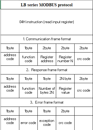
. I have documentation about the sensor's MODBUS protocol but I am unclear on how to utilize it with the libraries available as they cater towards another rs485 to ttl module that has the pins DI DE RE RO .
Can I use the Rx/Tx pins available on my ttl module with existing libraries such as Modbus Master.
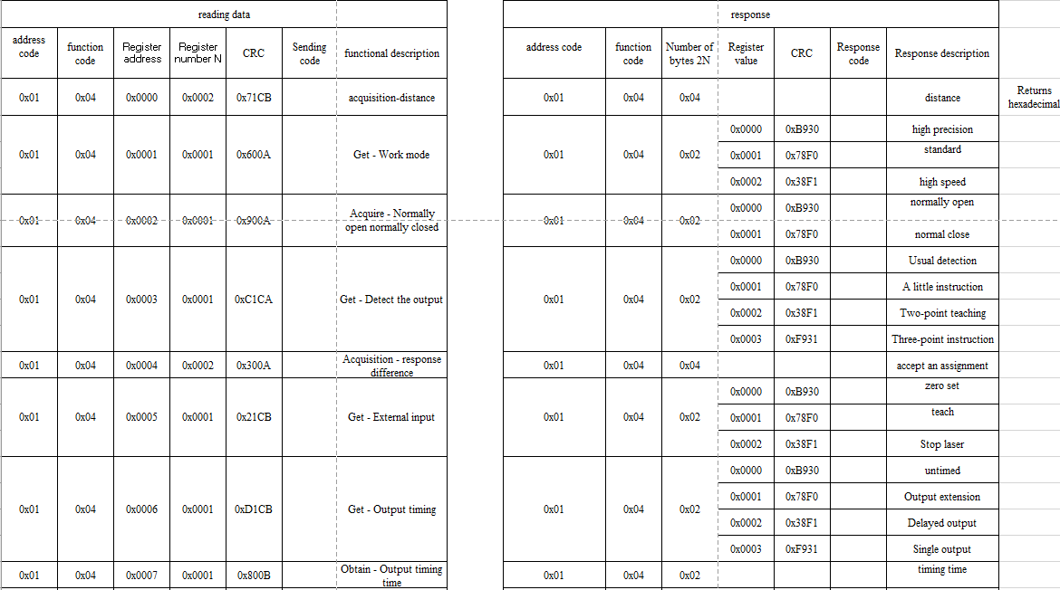
How do I access the sensor data using the given documentation about addresses and function codes.
Any coding that I can refer to either create my own library or to read the data directly from an industrial sensor with an RS485 is appreciated.
Mods I do not know if this is a cross-post to my previous question or not.
Please do tell me what other information I should provide. I am currently trying to understand the examples in the SensorModbusMaster library.
/*****************************************************************************
GetValues.ino

This example writes a setting value to a holding register, reads it to confirm
the value has changed, and then reads several data values from holding registers.

The register numbers in this example happen to be for an S::CAN oxy::lyser.
*****************************************************************************/

// ---------------------------------------------------------------------------
// Include the base required libraries
// ---------------------------------------------------------------------------
#include <Arduino.h>
#include <SensorModbusMaster.h>

// ---------------------------------------------------------------------------
// Set up the sensor specific information
//   ie, pin locations, addresses, calibrations and related settings
// ---------------------------------------------------------------------------

// Define the sensor's modbus address
byte modbusAddress = 0x01;   // The sensor's modbus address, or SlaveID
long modbusBaudRate = 38400; // The baud rate the sensor uses

// Define pin number variables
const int sensorPwrPin = 10;  // The pin sending power to the sensor
const int adapterPwrPin = 22; // The pin sending power to the RS485 adapter
const int DEREPin = 7;       // The pin controlling Recieve Enable and Driver Enable
                              // on the RS485 adapter, if applicable (else, -1)
                              // Setting HIGH enables the driver (arduino) to send text
                              // Setting LOW enables the receiver (sensor) to send text

// Construct software serial object for Modbus
#if defined(ARDUINO_AVR_UNO)
// The Uno only has 1 hardware serial port, which is dedicated to comunication with the computer
// If using an Uno, you will be restricted to using AltSofSerial or SoftwareSerial
#include <SoftwareSerial.h>
const int SSRxPin = 10; // Recieve pin for software serial (Rx on RS485 adapter)
const int SSTxPin = 11; // Send pin for software serial (Tx on RS485 adapter)
SoftwareSerial modbusSerial(SSRxPin, SSTxPin);
#else
// This is just a assigning another name to the same port, for convienence
// Unless it is unavailable, always prefer hardware serial.
HardwareSerial* modbusSerial = &Serial1;
#endif

// Construct the modbus instance
modbusMaster modbus;

// ---------------------------------------------------------------------------
// Main setup function
// ---------------------------------------------------------------------------
void setup()
{
    // Set various pins as needed
    if (DEREPin >= 0)
    {
        pinMode(DEREPin, OUTPUT);
    }
    if (sensorPwrPin >= 0)
    {
        pinMode(sensorPwrPin, OUTPUT);
        digitalWrite(sensorPwrPin, HIGH);
    }
    if (adapterPwrPin >= 0)
    {
        pinMode(adapterPwrPin, OUTPUT);
        digitalWrite(adapterPwrPin, HIGH);
    }

    // Turn on the "main" serial port for debugging via USB Serial Monitor
    Serial.begin(57600);

    // Turn on your modbus serial port
#if defined(ARDUINO_AVR_UNO)
    modbusSerial.begin(modbusBaudRate);
    // NOTE:  Software serial only supports 8N1
#else
    Serial1.begin(modbusBaudRate, SERIAL_8O1);
    // ^^ use this for 8 data bits - odd parity - 1 stop bit
    // Serial1.begin(modbusBaudRate, SERIAL_8E1);
    // ^^ use this for 8 data bits - even parity - 1 stop bit
    // Serial1.begin(modbusBaudRate, SERIAL_8N2);
    // ^^ use this for 8 data bits - no parity - 2 stop bits
    // Serial1.begin(modbusBaudRate);
    // ^^ use this for 8 data bits - no parity - 1 stop bits
    // Despite being technically "non-compliant" with the modbus specifications
    // 8N1 parity is very common.
#endif

    // Turn on debugging, if desired
    // modbus.setDebugStream(&Serial);

    // Start the modbus instance
    modbus.begin(modbusAddress, modbusSerial, DEREPin);

    // Write to a holding register
    // In this case, we are changing the output units of a dissolved oxygen sensor
    Serial.println("Setting DO units to ppm");
    modbus.int16ToRegister(0x01, 1, bigEndian);
    // Verify that the register changed
    // 0x03 = holding register
    // only holding registers are writeable
    int16_t doUnitMode = modbus.int16FromRegister(0x03, 0x01, bigEndian);
    Serial.print("Current unit mode is ");
    Serial.println(doUnitMode);
}

// ---------------------------------------------------------------------------
// Main setup function
// ---------------------------------------------------------------------------
void loop()
{
    // Get data values from read-only input registers (0x04)
    // Just for show, we will do the exact same thing 2 ways
    // All values will be read as bigEndian

    // Some variables to hold results
    uint16_t deviceStatus = 0;
    int16_t doPPM = 0;
    uint16_t temperature = 0;

    // Method 1:
    // Get three values one at a time from 3 different registers.
    // This code is easier to follow, but it requires more back-and-forth between
    // the Arduino and the sensor so it is a little "slower".
    deviceStatus = modbus.uint16FromRegister(0x04, 0x00, bigEndian);
    doPPM = modbus.int16FromRegister(0x04, 0x01, bigEndian);
    temperature = modbus.uint16FromRegister(0x04, 0x02, bigEndian);

    // Print results
    Serial.print("Device Status:");
    Serial.println(deviceStatus);
    Serial.print("Dissolved Oxygen in ppm:");
    Serial.println(doPPM);
    Serial.print("Temperature in °C:");
    Serial.println(temperature);
    Serial.println();

    // Method 2:
    // Read all three registers at once and parse the values from the response.
    // This is faster, especially when getting many readings, but it's trickier to
    // write and understand the code.
    bool success = modbus.getRegisters(0x04, 0x00, 3);
    // ^ This gets the values and stores them in an internal "frame" with the hex values of the response
    if (success)
    {
        deviceStatus = modbus.uint16FromFrame(bigEndian, 3);
        // ^ The first data value is at position 3 in the modbus response frame
        // 0 = modbus address, 1 = modbus method, 2 = # registers returned, 3 = 1st value returned
        doPPM = modbus.int16FromFrame(bigEndian, 5);
        // ^ The next data value is at position 5 since each register occupies 2 places
        temperature = modbus.uint16FromFrame(bigEndian, 7);
    }

    // Print results
    Serial.print("Device Status:");
    Serial.println(deviceStatus);
    Serial.print("Dissolved Oxygen in ppm:");
    Serial.println(doPPM);
    Serial.print("Temperature in °C:");
    Serial.println(temperature);
    Serial.println();
}