OLED display doesn't work with standalone ATmega328pu

OLED display (ssd1306) works fine with Arduino Uno, but it doesn't work with standalone ATmega328 extracted from the same Arduino Uno board. However blink sketch for LED D2 works with or without Arduino board connected, which I suppose means that power circuit and microcontroller are connected right. I can't understand what is wrong with I2C bus.

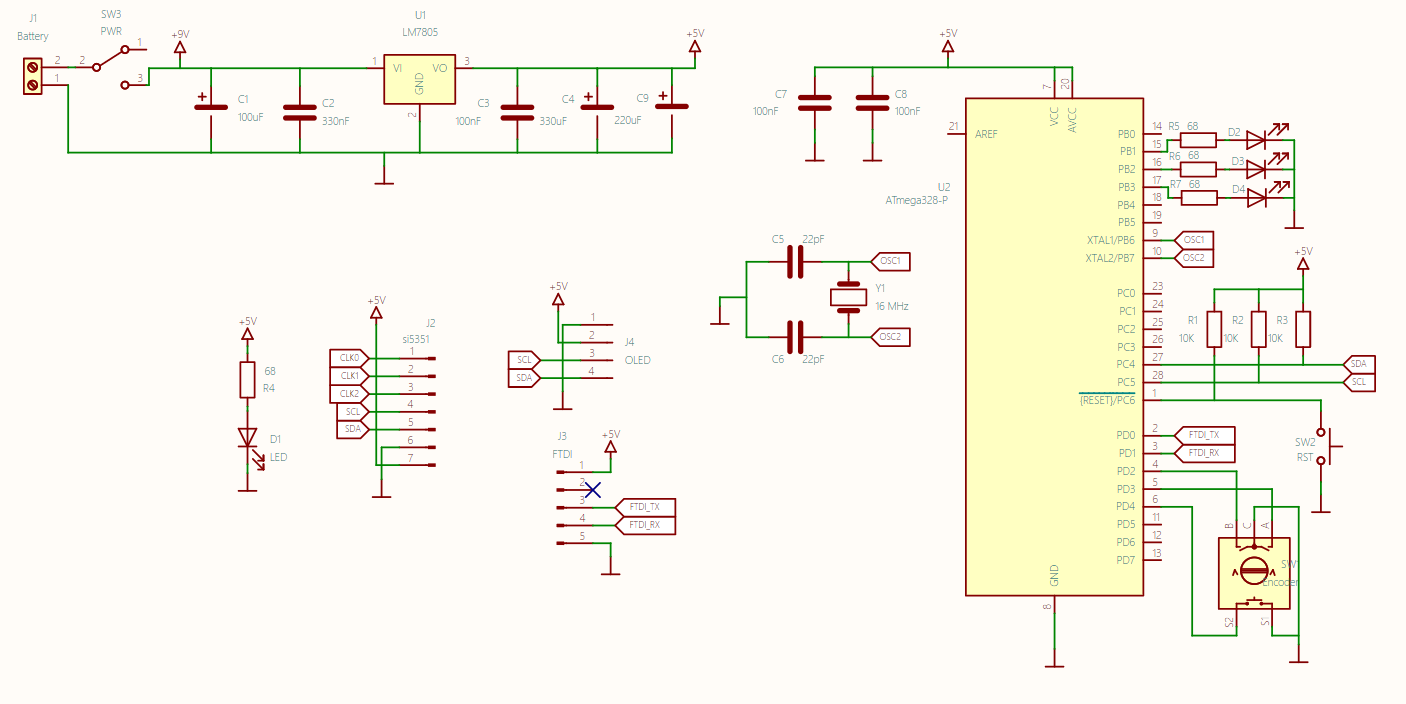
Here is my scheme. I also tried to remove R2, R3 pull up resistors, still no sign of OLED.

P.S I haven't connected si5351 to PCB yet

Does your sketch include Wire.h (seems to be used in all I2C code) and have you tried an I2C input device (DHT, for example)?

1 Like

Are you using a 9V battery ? That is not enough for the ATmega328P and certainly not enough for the OLED. Maybe for a few minutes.

What is the calculation that results in a resistor value of 68 Ω.

Can you show a photo with the wiring ?

Can you show the PCB layout file ?

Your OLED has a 3.3V I2C bus, unless it is a OLED from Adafruit.
The SCL should not be next to SDA, it is not that kind of bus.

1 Like

10k looks a bit high for I2C pull up resistors, try 4k7 or even 2k2 or similar.

68R for LED resistors are too low, maybe 220R or even up to 1k depending on the LED type and the brightness required.

1 Like

I am using 9V adapter, but thanks for your answer because I thought about moving to battery

I changed them to 220 Ohm

Fortunately it supports 5V :slight_smile: yes, it is from Adafruit

I didn't quite get it, can you explain please?

I solved the problem, had wrong resistor in wrong place

Thanks for your answer. Yes, everything is fine with code, some lines crossed where they should not in pcb layout, so I solved the problem. Everything works fine now

I'm glad you found the problem :smiley:

As you noticed, we did not see a big problem. Just a few details that needs to be fixed. You didn't show a photo or PCB layout, so I hope that the crystal with the two 22pF capacitors is close to the ATmega chip. The GND of the 22pF capacitors should be close to a GND pin of the ATmega chip.

The I2C bus was not designed to go through a cable. It can not deal with crosstalk between SDA and SCL. The worst possible situation is a flat ribbon cable with SDA next to SCL.
The I2C bus is a weak bus, the high level is created with pullup resistors.

Some see the word "bus" as assume that they can use the I2C bus to push data into a cable and that data comes out at the other end. The I2C is the opposite of that.

I have written more here: https://github.com/Koepel/How-to-use-the-Arduino-Wire-library/wiki/How-to-make-a-reliable-I2C-bus
Can you open that document UM10204.pdf and go to page 54 and read paragraph 7.5 ?
The official standard gives you 10 cm for the length of the I2C bus :exploding_head: If you want more length, then you have to know what you are doing.

2 Likes

This topic was automatically closed 180 days after the last reply. New replies are no longer allowed.