OLED ECG Circuit Not Displaying the Signal

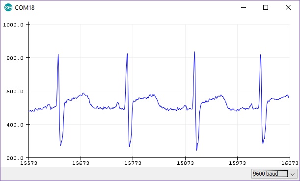
Hello all. I am attempting to use an ECG AD8232 with an OLED SH1106 128x64. The code compiles and I have wired everything correctly but it won't read the loop. The OLED screen starts up and displays the drawPixel but just stops there. I am expecting to see a signal for my heartrate. Are the any insights as to what could be going on here?

#include <SPI.h>
#include <Wire.h>
#include <Adafruit_GFX.h>
#include <Adafruit_SH110X.h>

/* Uncomment the initialize the I2C address , uncomment only one, If you get a totally blank screen try the other*/
#define i2c_Address 0x3c //initialize with the I2C addr 0x3C Typically eBay OLED's
//#define i2c_Address 0x3d //initialize with the I2C addr 0x3D Typically Adafruit OLED's

#define SCREEN_WIDTH 128 // OLED display width, in pixels
#define SCREEN_HEIGHT 64 // OLED display height, in pixels
#define OLED_RESET -1   //   QT-PY / XIAO
Adafruit_SH1106G display = Adafruit_SH1106G(SCREEN_WIDTH, SCREEN_HEIGHT, &Wire, OLED_RESET);


#define NUMFLAKES 10
#define XPOS 0
#define YPOS 1
#define DELTAY 2


#define LOGO16_GLCD_HEIGHT 16
#define LOGO16_GLCD_WIDTH  16
static const unsigned char PROGMEM logo16_glcd_bmp[] =
{ B00000000, B11000000,
  B00000001, B11000000,
  B00000001, B11000000,
  B00000011, B11100000,
  B11110011, B11100000,
  B11111110, B11111000,
  B01111110, B11111111,
  B00110011, B10011111,
  B00011111, B11111100,
  B00001101, B01110000,
  B00011011, B10100000,
  B00111111, B11100000,
  B00111111, B11110000,
  B01111100, B11110000,
  B01110000, B01110000,
  B00000000, B00110000
};


void setup() {
// initialize the serial communication:
Serial.begin(9600);
pinMode(10, INPUT); // Setup for leads off detection LO +
pinMode(11, INPUT); // Setup for leads off detection LO -

 delay(250); // wait for the OLED to power up
  display.begin(i2c_Address, true); // Address 0x3C default
 //display.setContrast (0); // dim display
 
  display.display();
  delay(2000);

  // Clear the buffer.
  display.clearDisplay();

   display.drawPixel(10, 10, SH110X_WHITE);
  // Show the display buffer on the hardware.
  // NOTE: You _must_ call display after making any drawing commands
  // to make them visible on the display hardware!
  display.display();
  delay(2000);
  display.clearDisplay();
}
 
void loop() {
 
if((digitalRead(10) == 1)||(digitalRead(11) == 1)){
display.print('!');
}
else{
// send the value of analog input 0:
Serial.print(analogRead(A0));
}
//Wait for a bit to keep serial data from saturating
delay(1);
}

If you read the code in setup(), and the comments, you will see why the manner in which you attempt to write to the OLED in the loop() function does not work.

// NOTE: You must call display after making any drawing commands

Have you written code that just uses the serial monitor to see what the ECG part is doing, or not doing?

Read some example sketches that use the OKED you have and see the little dance that making things show up on it.

Once you are up to speed on the two halves of this project combining them should be easier.

a7

See the inserted line here...

You have your "heartrate" inputs on digital pins. The pins will only register HIGH or LOW from your probes. Put your heartrate inputs on analog pins (A0 through A7). You will need to know the highest and lowest value of the probes (for example, highest = 2vdc, lowest -2vdc and map those values to the OLED.

If I'm correctly reading Sparkfun's example Heart Rate Display sketch that the parts of the code dealing with the sensor were taken from, the inputs are fine. D10 and D11 are just indicating whether or not the sensor pads are correctly attached to the body. The actual sensor output is coming in on A0.

The problems with the code are several:

  1. The text colour is never set to white in setup() with a call to display.setTextColor(SH110X_WHITE); as @xfpd noted.
  2. After the display.print('!') in loop, there is no display.display(); as @alto777 noted.
  3. After the initial bits cribbed from Adafruit's example code, the only time anything is being sent to the display is when one of the pads isn't correctly connected, and an ! is sent. At no time is the value of the sensor (from A0) being sent to the display. And in any case, at a 1ms refresh rate, the numbers would be changing so fast that it'd be illegible anyhow -- and you'd likely spend more time than that just to refresh the display.

When you say

I am expecting to see a signal for my heartrate

are you thinking that you're going to see a graph like the Serial Plotter shows?


If so, you've got a lot more code to add to make that happen. This library might be helpful.

A simple sketch showing "analog input" as the heartrate on the OLED. If you leave the dials at "center", you will see a simple "retrace"... where I clear a vertical line a xVal to erase the old trace.

#include <Adafruit_GFX.h>
#include <Adafruit_SH110X.h>

#define i2c_Address 0x3c //initialize with the I2C addr 0x3C
//#define i2c_Address 0x3d //initialize with the I2C addr 0x3D

#define SCREEN_WIDTH 128 // OLED display width, in pixels
#define SCREEN_HEIGHT 64 // OLED display height, in pixels
#define SCREEN_MIDDLE 32 // to display trace at screen middle
#define OLED_RESET -1    // QT-PY / XIAO
Adafruit_SH1106G display = Adafruit_SH1106G(SCREEN_WIDTH, SCREEN_HEIGHT, &Wire, OLED_RESET);

int xVal = 0; // trace location. left edge of OLED = 0

void setup() {
  Serial.begin(9600); // initialize serial communication:
  pinMode(A0, INPUT); // Setup for leads off detection LO +
  pinMode(A1, INPUT); // Setup for leads off detection LO -

  delay(250); // wait for the OLED to power up
  display.begin(i2c_Address, true); // Address 0x3C default
  display.setTextColor(SH110X_WHITE); // TEXT color, not PIXEL color
  display.clearDisplay();  // Clear the buffer.
  display.display();
}

void loop() {
  int yVal = map(analogRead(A0), 0, 1023, 6, -6); // INPUT min/max
  int zVal = map(analogRead(A1), 0, 1023, 1, 5); // AMPLITUDE adjust

  display.drawLine(xVal, 0, xVal, 63, SH110X_BLACK); // verticle line to erase old trace
  display.drawPixel(xVal - 1, SCREEN_MIDDLE + (yVal * zVal), SH110X_WHITE); // the trace
  display.display();

  xVal++; // move to next pixel
  if (xVal == 128) { // if at OLED right edge
    xVal = 0; // reset xVal to left edge
  }

  delay(20); // 20ms is about 4 seconds per trace
}

ok I see. I have been able to get a signal onto the OLED with a lot of changes to the code. Those links will be very helpful because the signal is not clean at all. Thank you very much.

Be sure to use the correct library for the SH11xx OLED. Post an image or video of the "not clean" trace... and your sketch. : )

This topic was automatically closed 180 days after the last reply. New replies are no longer allowed.