Hi Guys!
I would like to create a power latching circuit for a MCU, where I can use the switch as a digital input (GPIO) after turning on the circuit. Does anyone have a ready-made solution for this?
Thank you very much!
Hi Guys!
I would like to create a power latching circuit for a MCU, where I can use the switch as a digital input (GPIO) after turning on the circuit. Does anyone have a ready-made solution for this?
Thank you very much!
Hello fl11
Try this:
if ((digtialRead(ButtonPin)==HIGH) and (digitalRead(LedPin)==LOW)) digitalWrite(LedPin,HIGH);
HTH
See this epic thread, I believe it ends up with a latching power switch that can also be used as input to the sketch once it has begun.
Or google. There are many circuits that do this in various ways.
HTH
a7
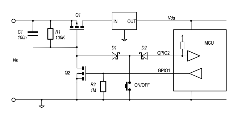
Thank you! I found a very good website (https://circuitcellar.com/resources/quickbits/soft-latching-power-circuits/) where they have descriptions of several circuits. The middle solution would be just right (picture attached). I would like to ask for your help with sizing the components (resistors, capacitors, transistors).
I would work with a 5-volt input voltage and use a 5-volt ESP32 MCU, so I would skip the internal voltage regulator part.
Sry, eyes off the ball.
I can't help you with the circuit you selected, but I can say that this:
is what I would use instead.
Just feed your 5 volt supply to the battery input, and take your 5 volt switched power off the controlled battery output line.
You can see the similarity to the circuit you posted. It probably has a few tricks and stuff, feel free to take a few days and slog through the previous 351 (!) posts on that thread.
I do not believe @er_name_not_found is collecting royalties.
a7
Thank you!
Community effort, community knowledge
@fl11 somewhere in that thread you'll find code.
Refer to the last few dozen posts for the latest schematics
I haven't followed the other thread, but I don't see anything wrong with using the N-channel mosfet. I don't see what the NPN would contribute.
Feel free to help @fl11 with specific parts and so forth for the schematic posted in #4 above.
And make what you will of this
I replaced the N-MOS with a BJT because at T=0 the BJT will be completely off, unlike the N-MOS.
The reasoning offered on the other thread.
a7
I couldn't find a circuit in the other thread where the N-channel would be partially on. So I don't know what he was talking about.
I think the circuit in #4 is fine. If he can find one, a DMP1045U should work for the P-channel, and a 2N7000 or BS170 should work for the N-channel.
The diodes could be just 1N4148 I think.
Hi!
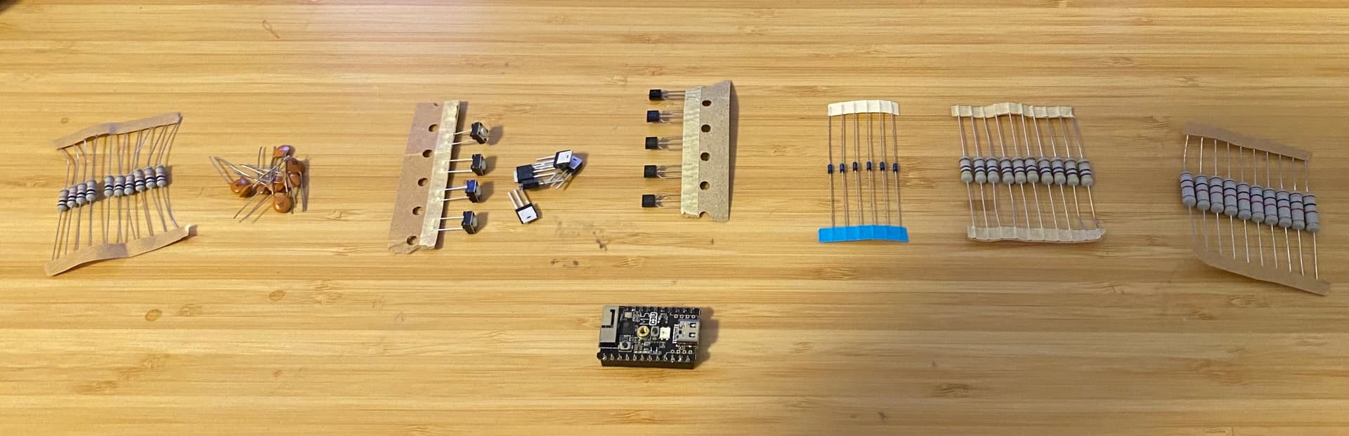
I bought the parts, and in the evening, I will solder the circuit on a prototype board. I hope everything will work well! Thank you very much for your help so far!
In a completely discharged state, a MOSFET floats and will allow one sizable burst of power through when the voltage source is connected. There is a cap that eliminates the width of the burst, but swapping the MOSFET on the gate with a BJT eliminates it completely as it is definitively off in a discharged state and as such provides a determined state for the power switching MOSFET.
I'm still confused. Are you talking about the N-channel mosfet? In the mosfet circuit I found in that thread, it has a pulldown resistor to ground. So it's not floating. Could you point me to the post number in that thread that has the floating gate mosfet you're talking about?
If you're talking about the P-channel mosfet, then yes, when power is first applied, it can turn on because the gate lags in coming up. The capacitor prevents that by bringing the gate up with the source, keeping the mosfet turned off. But I don't see what difference an N-channel or an NPN on the gate makes. Either would be off.
Well, I'm just late to that discussion, so if the OP understands what you mean, that should be good enough.
Hello!
I have assembled the circuit, measured everything twice, the wiring is correct, and without the MCU, the circuit seems to be working fine. If I pull the "power hold" pin to 5 volts, it holds the voltage, and when I release it, the output turns off. Unfortunately, when I connect the MCU to the system, I can only successfully turn it on about once in every ten attempts. Without a latch circuit and with a 5-volt input, the "power hold pin" perfectly holds the 3.3V voltage immediately after booting.
The list of components:
bjt: 2N3904
p-mosfet: IRFU9024
Instead of the 480-ohm resistor, I could only obtain a 470-ohm resistor.
Guys!
I did it! I rerouted the Power Hold Pin to GPIO10 instead of GPIO9! All functions are working perfectly! I forgot to mention that the MCU is an M5STAMP C3, equipped with esp32 c3.
Thank you for your help so far!
Which circuit and parts did you land up with?
a7
I used the circuit of @er_name_not_found , but instead of the P MOSFET, I used a different type, and I used a 480 Ohm resistor instead of the 470 Ohm one. All the other components are the same. The next step is to build a DC-DC boost converter circuit to have a stable 5V output from 2 AAA batteries.
THX.
Careful. The regulator will use power unless it has a shutdown mode, so it might have to be after your power switch.
Careful - will that power switch work at 3 volts? Will the pushbutton still be able to provide power control and subsequently serve as an input button?
a7
Ahh, thx!
Then I think I need to do further research, any tips on where to start? ![]() Thank you very much!
Thank you very much!
On my first quick search, I found a DC-DC boost converter that seems suitable, which has a CE (chip enable) pin and theoretically meets my specifications as well. (and it's available for personal pickup within 1 day ![]() )
)
NCP1402
Micropower PFM Step-Up
DC-DC Converter