I have been working on a home cockpit and made some good progress this weekend. All the panel switches, gear lever, brake and fuel selector switches are working. Those have been pretty easy.
However, I’ve come across a more complicated (for me) situation.
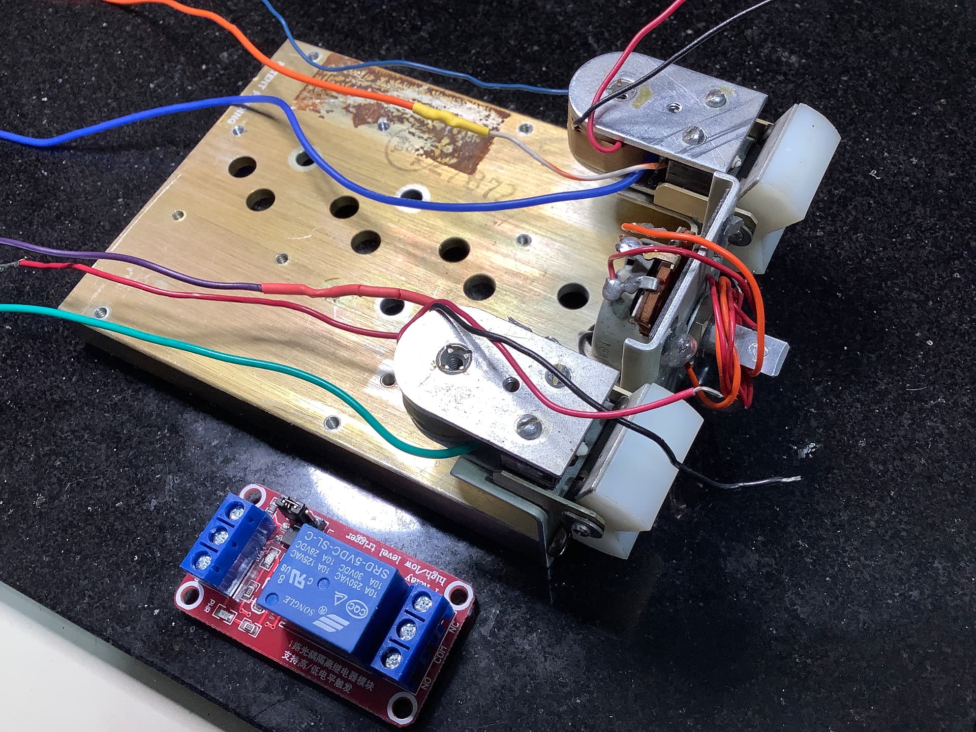
The autopilot module I am trying to connect has two switches, each are a momentary with NO and NC wiring (3 wires). So I have two circuits with each switch.
When the switch is closed it has to simultaneously activate a relay to turn on the electromagnet holding the rocker in place and at the same time activate a pin that will turn on the autopilot in the flight sim.
I am not sure how to approach this problem.
Is it possible to have the one NO switch when closed do double duty, i.e. switch on the magnet and the autopilot at the same time?
Or does it make sense that in the NC position it can activate the relay to turn off the magnet and when the NO switch is opened again it turns off the autopilot. The autopilot operation will be a function of Air Manager LUA coding that I will have to develop. But the idea here is to understand how to use the switch and the Arduino pins to do these two things more or less at the same time.
It's up to your sketch what to do if it recognizes that the switch is closed. You can do whatever you want - one action or more.
If it is in fact a momentary switch then you'll need to keep a little state information to keep track of whether autopilot is on or off. Is there an indicator light to control too?
I will try connecting that switch to a couple of LEDs using an Arduino sketch. I think the idea is that when the switch is normally open it will light up one of the LEDs and when closed the other one will light. Pretty easy and by using a separate pin for each circuit.
However, I don’t think I can get the flight sim programming to activate a relay. Air Manager is the flight sim LUA program that will connect an Arduino pin to a switch in the flight sim. I will have to do some research on that.
If I can’t get the LUA to connect to the relay, the IDE would need to be used to drive that relay for the magnet….I assume.
The problem I see is that I need two different programs to do two different things from the same switch. An impossibility?
Can two Arduinos, one for the NO side of the switch and one for the NC side, be used since they each need to connect to different programming?
Could the two arduinos share the common?
No light needed.
Start with a state diagram: like a logic table. From that extend the closed-open states to identify areas (and variables) that the Arduino must track and what the Arduino response will be for each state.
This sounds more like a toggle switch to me - can you post a link or picture?
@MicroBahner's point stands though - once you detect the state of the switch (or perhaps that it just changed) you can have a single Arduino do eighty five things if you like. It feels like you may be making this harder than it needs to be.
Hello
Design and post a schematic with all used components to identify the physical interfaces and their dependencies.
I am sure it’s easier than I think. Give me a few hours and I might be able to create a schematic. I’ll have to find, install and learn some type of schematic diagramming program first.
It's perfectly acceptable to draw it manually on paper and post a photo of it.
This is the best I can do with what I know. Each part is easy enough. I think I understand the concept of how to energize the magnet with a relay via the IDE and I understand how I can use the momentary switch without the magnet to assign a pin by using Air Manager LUA code to send data back and forth to the simulator. But please let me know if I have any or all of this completely wrong.
Trying to do both with the same switch has my head spinning.
EDIT: I created an IDE sketch using the internal pull-ups to alternately turn on one of two LEDs with the momentary switch closed or opened.

So I think what's happening is that there are two spring loaded rocker switches in the initial picture. One of them controls the autopilot and when it is pressed, the Arduino must activate the electromagnet to keep it pressed. At the same time it must tell the Flight Sim that autopilot is now on.
I would set an Arduino input as input_pullup and wire it to the NO contact. Run a ground wire to the common contact. Poll the input. Look at the state change example in the IDE, so you can see how to do something when the button BECOMES pressed. Note that pressed will show up as LOW.
At that point, use the relay to lock the rocker in place. Then send a message to the sim to say turn autopilot on.
Worry about turning it off when that's working, but you just need to see that the button is no longer attached to NO and reverse the process.
Yes the rocker switches do have a spring on the bottom. The operation of the IDE sketch I have working with the button states and the internal pull-ups albeit operating two separate LEDs. I just need to replace one LED with the relay and the other one with…..what. The problem with connecting the “other” to the flight sim is that the IDE can’t tell the autopilot to turn on or off. That is handled by a different software called Air Manager and it’s LUA scripts. So how to send the same button push to both IDE / relay and to Air Manager.
EDIT: I can also connect that switch to My flight sim with AirManager and my Arduino micro. It’s set to pin 8 and the switch will activate any Air Manager hardware that is set to the same pin. Easy stuff, except there is no pre-made hardware for an autopilot switch. Something I will have to write myself.
In sim software I've seen before, the Arduino talks to the sim via one communication mechanism. UDP or serial and it can send multiple channels that way. Does air manager need one pin on the Arduino per button on your cockpit hardware?
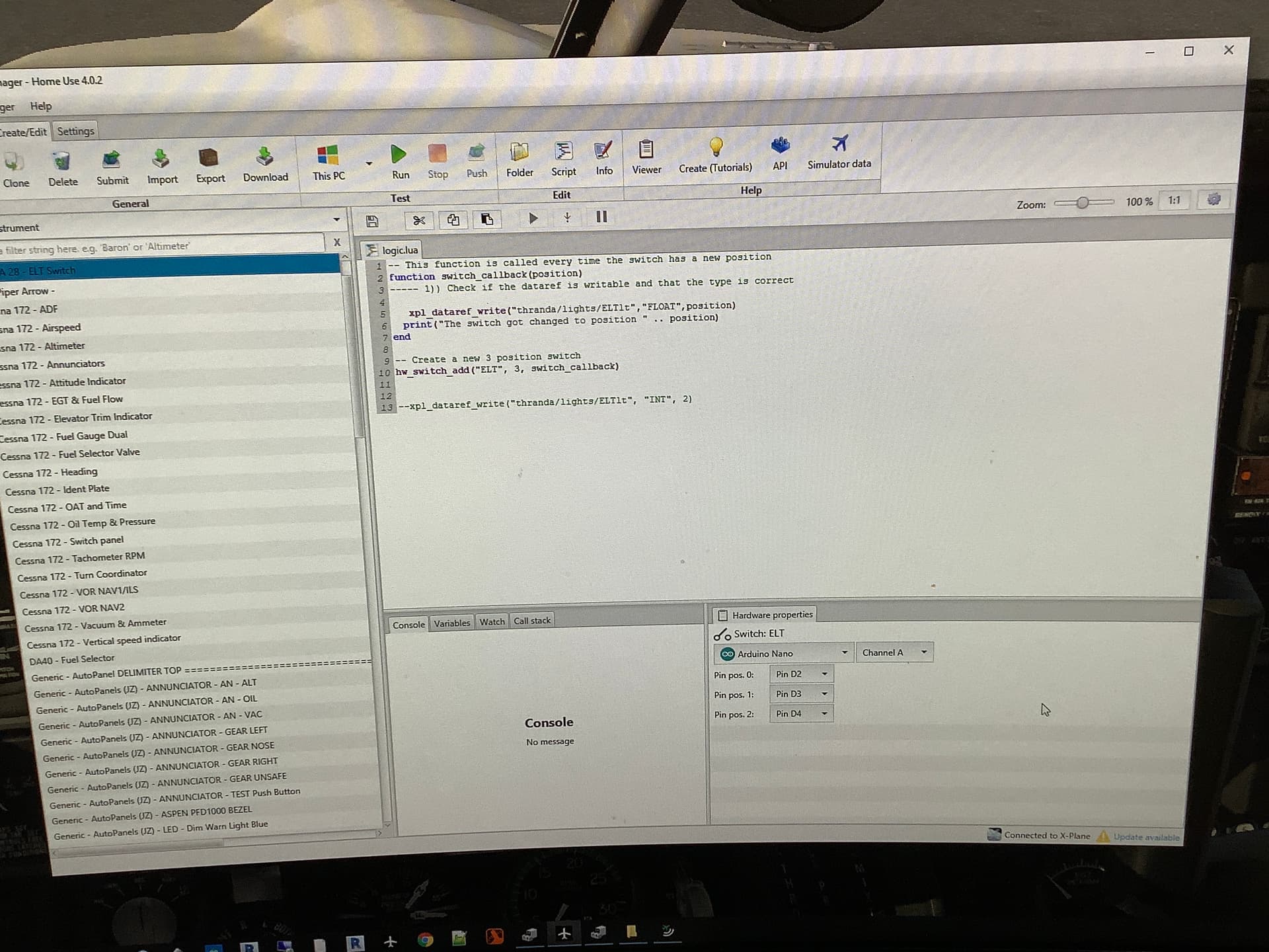
Yes that is basically how Air Manager works. There are other flight sim programming options like Mobiflight and SimVimX. They all have programming code that communicates with the flight sims like Xplane, and MSFS 2020. The code takes the input from the Arduino pins and then runs the corresponding code to operate that item in the sim. In this case for the ELT “hardware” I have a physical 3 way switch that is connected to pins 2,3 and 4 on a Nano.
I'll guess that you're using Air Manager's standard Arduino mode with their code on the Arduino talking to Lua on the PC.
The folks answering your questions (including myself) were thinking you were writing custom code on the Arduino. From my vast experience of Air Manager (five minutes of scanning their documentation) it looks like you can do more complex stuff using MessagePort, but it would be rather more work.
I think you're going to need more specialist help here - we see folks building panels occasionally, but I hadn't come across Air Manager before you mentioned it.
Are you building a sim for a particular aircraft?
The sim is based on a Piper Arrow.
This autopilot function is indeed a complicated issue with having to use the magnets to hold the switch closed. The only reason for that is that I want to use those exact rockers. There are no other standard switches that will have that look.
If I can’t find a solution to using the existing magnets, then I have a simpler low-tech solution.
Placing thin round earth magnets on top of the electromagnets transfers enough of a magnetic field into the top plates to hold the top of the rocker and thereby keeping the button pushed in.
I am beginning to think I need to go that route.
You might be able to do it from Lua. If you have the switch defined in Lua, your callback will get called when it's pressed. If you define something like an LED too, you can set its state in that callback. But in actuality, that LED will be the relay that controls the electromagnet.
There may be a more appropriate object provided by Air Manager, but all you need is on & off, so a LED would do I think.
I am going through the multiple Air Manager tutorials relative to Xplane but I am having some issues with getting things to work.
The layout of Air Manager when those videos were made is different from the current version and makes things difficult.
I have yet to get to a point on how to use LUA to turn on LEDs which is exactly what I was able to utilize in IDE for the relay. I will look into finding examples of how the LUA scripts can write to LEDs.