So I am using a solar charger (MPPT) attached to the battery pack (18650 pack) that's attached to an Arduino. it works fantastically but my problem is when it dies and the sun starts coming up it charges slowly and that slowly raises the voltage causing the Arduino to go into bootloader mode and not work until I reset manually.
My question is is there a way to stop the voltage flow from the battery to Arduino until a minimum threshold is met? min is ~2.7V for my needs.
I have done some quick light searches of similar questions and one said a Zener Diode put in backwards? I don't know if it would be good for the diode to be constantly forced to flow in reverse...
another said a Schmitt trigger??? I don't even know what that is aside from Wikipedia...
and the one I like the most said use a Mosfet. I don't know any circuitry behind this tho...
essentially what it is is a battery cutoff? I need the power to flow to Arduino only when V > ~2.7
You'd need a low-power comparator or comparators and some sort of switching device. Then
you will get clean switching and can set the hysteresis through resistor choice.
Ok, thank you so I think a Reset controller would be the best way to go, hows this one I found on Adafruit? KA75330
I think this would work if I connected Pin 3 to the RST on the esp32 I'm using and pin 2 to GND then when Pin 1 hits 3.3V the board would be allowed to boot.
My only problem is id like a lower threshold voltage. something more like 2.7 as I mentioned earlier are there any suggestions?
I think I may have it but I'd like more opinions than just mine lol.
what about this KA75250 or this KA75270 ??? they appear to be the same as the Adafruit one but for 2.5 and 2.7 volts respectively and that's EXACTLY the range id like I just hope I'm understanding how they function correctly and I'm not going down the wrong path so correct me, please
Hi,
Can you please post a copy of your complete circuit please?
If you are letting your battery pack get so low, you need to detect the low battery level and disconnect your controller.
How low voltage does your battery pack get to?
Have you got protection on the battery to protect it against over discharge?
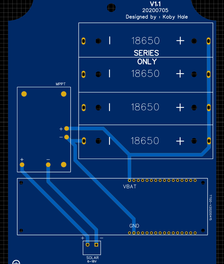
I'm using 18650s in a pack in parallel so 3.7v connected to a TTGO sim7000G over VBAT pin (3.7v battery pin). That's basically it. I have a solar charger also attached to the battery pack for charging. MPPT
there Is no over-discharge protection right now because I was under the impression that the TTGO had it built in but that is only for the battery pack on the back. which we cant use easily since we fabricated a PCB that the board sockets into so no back access AND they still have the problem of the MCU locking when powering on at a low voltage...
Using a reset controller that holds the Arduino in "off-mode" should function as over-discharge protection since the board can no longer draw power if its held off once batteries are at 2.7v, aside from maybe a tiny amount which I don't think will hurt the batteries that bad by the time the sun peaks. also, they should NEVER get that low since the board uses about 0.2v per day and the solar charger tops that off in like 10 min of shady sun of like 2 in full sun. This is all just worst-case prep I guess... the pack is good for 6.9~8.2 days no charge from testing so only a 7-day storm will make it die and we don't ever get those, usually.
If you have any more questions or feel that's not enough info please ask more.
Well as I said its kind of on a PCB
1st photo is a cleaned-up version of the PCB (Removed all but power lines)
2nd is a render that I find easier to look at (Battery - connects the 4 on the back)
So I've been reading some more and would adding an STM1061N27WX6F solve it? It has 3 pins. P1 input, P2, GND, P3 Output. When P1 voltage is greater then 2.7v then P3 is HIGH otherwise its LOW, So if I where to connect P3 to RST on the esp and P1 to my battery with some smoothing caps then, If I'm thinking correctly when voltage drops bellow 2.7v p3 will switch to LOW pulling RST to LOW forcing the esp into a "Forced off" state. Then when the batteries charge up above 2.7v p3 would be HIGH and the esp would boot normally. Right????.... That's exactly how adafruit does it with there's except the voltage threshold is 3.3v.
the description of the one they sell is sounding exactly like my problem
maybe your battery is already drained and you're trying to charge it back up, but as you are trying to charge it up, the ESP turns on and the spike of current drains the battery immediately so it never gets through the trickle-charging stage.
This little chip is a simple solution: It monitors the voltage on one Input pin, and when that voltage goes below 3.3V, it will pull the output pin low. If you connect that Output pin to the Enable pin on the ESP, it will make sure that the ESP does not run if the battery dips too low.
I just want to make sure what I'm doing isn't going to damage anything and that's even logical to begin with