Hello! I am pretty new to this stuff so I'm probably missing something pretty obvious, but I cant seem to make my lcd display show anything that I have coded it to.
Some pictures:
For an I2C LCD display to work, the I2C address and the I2C backpack to LCD pin mapping must be correct. If the library default settings for either or both are not correct the LCD will not work. You can try to figure out the right pin mapping and use an I2C scanner to find the address, but if you install and use the hd44780 library that is done automatically by the library.
To install the hd44780 library. The hd44780 library is the best available for I2C LCDs. The library is available in the Library Manager. Go to Library Manager (in the IDE menus, Sketch, Include Libraries, Manage Libraries) and in the Topics dropdown choose Display and in the Filter your search box enter hd44780. Select and install the hd44780 library by Bill Perry.
The class that you want to use is the hd44780_I2Cexp class. There are examples to show how to use the library. The nice thing about the hd44780 library is that it will autodetect the I2C address and the I2C backpack to LCD pin mapping.
In the examples, there is a diagnostic sketch that will help us to help you if you still have trouble with the display. Run the diagnostic sketch and post the results.
Hi @tishadev.
In the IDE examples you will find the sketch "i2c_scannr.ino".
Load and run it and see on the serial monitor if your backpack's address appears and if it's really 0x27.
Hello and thanks for the quick response. I installed the library but I cant find the example your talking about, can you please send me the directory of it or the example itself? Thanks.
The hd44780 library comes with lots of documentation.
It is in the Documentation sketch.
It has clickable links in the comment at the top of the sketch.
I think it is much easier to run the I2CexpDiag sketch that comes with the hd44780 library and it will test everything and printout information relating to any issues it finds.
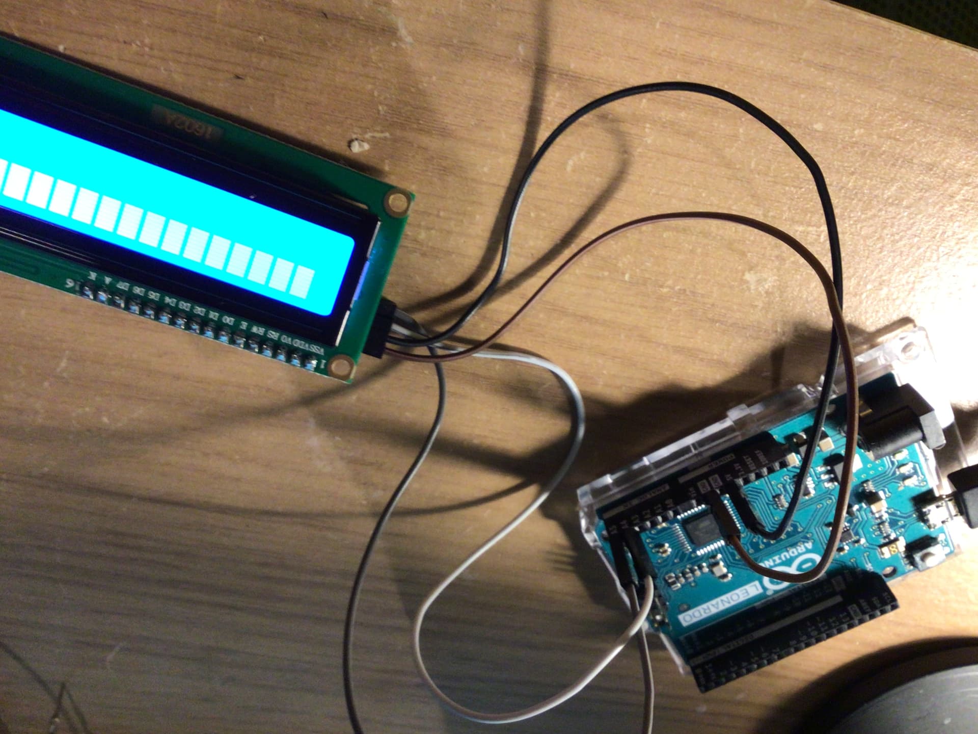
Notice that the boards (both the UNO and the Leonardo) have header pins specifically labeled SCL and SDA. If you use those, they will be connected to whatever pins are actually used for the I2C bus (good if you are making a shield you want to be multi-board compatible).
This output posted is is not from the I2C scanner.
The output is from the hd44780 library I2CexpDiag sketch.
Look at the output.
You can see that the SDA signal is on digital pin 2 and SCL is on digital pin 3 vs A4 and A5.
This is one of the values of using I2CexpDiag.
It shows you which pins to use.