Hi, @BogdanSikach
Can I suggest on your next board you put indicator LEDs, for the 24V, 12V and 5V supplies, and LEDs for each of the FGZ sensors so you can see at a glance the state of your inputs.
Good to see your use of bypass capacitors. ![]()
![]()
![]()
![]()
![]()
Hi, @BogdanSikach
Can I suggest on your next board you put indicator LEDs, for the 24V, 12V and 5V supplies, and LEDs for each of the FGZ sensors so you can see at a glance the state of your inputs.
Good to see your use of bypass capacitors. ![]()
![]()
![]()
![]()
![]()
Please post your using code tags. It's probably a software problem.
I won't open a zip as it may have a virus.
Why did you delete the schematics from post #1 were they wrong?
Many people that have already replied may have been referencing your original schematic
Looks to me like you have no current limiting resistors on the input to the opto switch.
In my opinion that is why things are shutting down, because you are sending too much current to the IR LED inside the switch. In time I believe you will break the Arduino and severely limit the amount of IR light the transmit side will produce.
The reason for a zip is because the code is not a single file but a structure of files. Ok. I will paste code in a markdown format.
No schematics is the same, but I added some annotations only as asked.
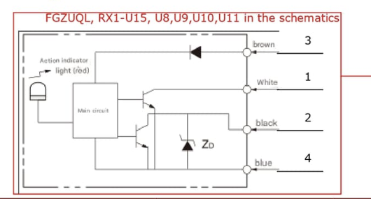
What is the relationship between pins 1,2,3,4 and the wires brown, white, black, blue?
Thank you for your comprehensive answer.
If the fault did not occur with the four sensors disconnected, its obvious.
Yes but a) they are powered from 12V bus, not 5V arduino, and b) their inputs (i.e. outputs) have a 1k pull up. Which means the current is 5mA max per a sensor.
I would say the regulator is going into thermal shutdown.
As I said the temperature is about 50C, according to the spec of regulator it is quite in range. But I will monitor the temperature more carefully maybe.
Instead of 24V to 12V DC-DC converter, use a 24V to 5V Dc-DC converter and feed 5V DIRECTY into the Nano 5V pin and to the peripherals.
Yeah, probably then I will be able to power sensors from 24V, and arduino and periphs from 5V. Will consider this option.
What else is the 5V supply powering?
Directly nothing but everything on the schematics. However, the alarm pin (D2) is connected to the optocouple through a resistor of 200 Ohm (so limiting the current to 25 mA).
Can I suggest on your next board you put indicator LEDs, for the 24V, 12V and 5V supplies, and LEDs for each of the FGZ sensors so you can see at a glance the state of your inputs.
Yeah, now I understand I should've put some debugging stuff there ![]()
I have. There are 1k pullups there. Means current is 5mA max. Or do you mean the power pins ?
The zip file in post 1 contains four files with code:
alarm_module.ino
#include "description.hpp"
#include "Temperature.hpp"

using namespace table5d;

enum EAlarm_t : uint8_t
{
    eNone        = 0x00,
    eTemperature = 0x01,
    eOpto        = 0x02,
};

Bus<description::temperature::board::numberOfSensors> boardTemperature(
  description::temperature::board::pin,
  description::temperature::board::alarmHigh,
  description::temperature::board::alarmLow,
  description::temperature::board::resolution
);

Bus<description::temperature::motors::numberOfSensors> motorTemperature(
  description::temperature::motors::pin,
  description::temperature::motors::alarmHigh,
  description::temperature::motors::alarmLow,
  description::temperature::motors::resolution
);

namespace alarm
{
  void check();
  void set(const EAlarm_t reason);
  void unset(const EAlarm_t reason);
  EAlarm_t status = EAlarm_t::eNone;
  ms_t lastCheck = 0;
}

void setup()
{
  Serial.begin(115200);

  pinMode(description::alarm::pin,  OUTPUT);
  pinMode(description::opto::pin,   INPUT_PULLUP);

  boardTemperature.init();
  motorTemperature.init();
}

void loop()
{
  boardTemperature.update();
  motorTemperature.update();

  if(boardTemperature.error() != EErrorCode::eNone)
    alarm::set(EAlarm_t::eTemperature);

  if(motorTemperature.error() != EErrorCode::eNone)
    alarm::set(EAlarm_t::eTemperature);

  if(motorTemperature.alarm() or boardTemperature.alarm())
    alarm::set(EAlarm_t::eTemperature);

  if(PIND & _BV(description::opto::pin))
    alarm::set(EAlarm_t::eOpto);

  alarm::check();
}

void alarm::set(const EAlarm_t reason)
{
  status |= reason;
}

void alarm::unset(const EAlarm_t reason)
{
  status &= ~reason;
}

void alarm::check()
{
  if(millis() - lastCheck > 1000)
  {
    Serial.print("Global: ");
    Serial.print(status);

    lastCheck = millis();
  }

  if(status != EAlarm_t::eNone)
    PORTD |= _BV(description::alarm::pin);
  else
    PORTD &= ~_BV(description::alarm::pin);

  status = EAlarm_t::eNone;
}
Core.hpp
#pragma once

namespace table5d
{
    typedef unsigned long ms_t; // for millis
}
description.hpp
#include "Temperature.hpp"

using namespace table5d;

namespace description
{
    namespace temperature
    {
        namespace board
        {
            constexpr uint8_t       pin             = A1;
            constexpr int8_t        alarmHigh       = 30;
            constexpr int8_t        alarmLow        = 0;
            constexpr EResolution   resolution      = EResolution::e9bit;
            constexpr uint8_t       numberOfSensors = 1;
        }

        namespace motors
        {
            constexpr uint8_t       pin             = 8;
            constexpr int8_t        alarmHigh       = 30;
            constexpr int8_t        alarmLow        = 0;
            constexpr EResolution   resolution      = EResolution::e9bit;
            constexpr uint8_t       numberOfSensors = 2;
        }
    }

    namespace opto
    {
        constexpr uint8_t pin = 5;
    }

    namespace alarm
    {
        constexpr uint8_t pin = 2;
    }
}
Temperature.hpp
#pragma once

#include "Arduino.h"
#include "Core.hpp"
#include "OneWire.h"
#include "DallasTemperature.h"

namespace table5d
{
    enum EConversionTime : ms_t
    {
        e95ms   = 100,
        e190ms  = 200,
        e375ms  = 400,
        e750ms  = 800,
    };

    enum EResolution : uint8_t
    {
        e9bit   = 9,
        e10bit  = 10,
        e11bit  = 11,
        e12bit  = 12,
    };

    enum EErrorCode : uint8_t
    {
        eNone                   = 0x00,
        eNotInitialized         = 0x01,
        eConfigFailed           = 0x02,
        eIncorrectDeviceCount   = 0x04,
        eConnectionError        = 0x08,
    };

    inline EConversionTime resolution2time (const EResolution resolution)
    {
        switch(resolution)
        {
            case EResolution::e9bit  : return EConversionTime::e95ms;
            case EResolution::e10bit : return EConversionTime::e190ms;
            case EResolution::e11bit : return EConversionTime::e375ms;
            case EResolution::e12bit : return EConversionTime::e750ms;

            default : return EConversionTime::e750ms;
        }
    }

    inline EResolution time2resolution (const EConversionTime time)
    {
        switch(time)
        {
            case EConversionTime::e95ms  : return EResolution::e9bit;
            case EConversionTime::e190ms : return EResolution::e10bit;
            case EConversionTime::e375ms : return EResolution::e11bit;
            case EConversionTime::e750ms : return EResolution::e12bit;

            default : return EResolution::e12bit;
        }
    }

    template<uint8_t N>
    class Bus
    {
        public :
            static constexpr uint8_t numberOfSensors = N;


            static constexpr uint8_t strongErrorMask =
                eNotInitialized |
                eConfigFailed |
                eIncorrectDeviceCount;

        private :
            OneWire             m_wire;
            DallasTemperature   m_dallas;
            DeviceAddress       m_address[N]    { 0 };
            ms_t                m_timeStamp     { 0 };
            uint8_t             m_pin           { 0 };
            int8_t              m_alarmHigh     { 90 };
            int8_t              m_alarmLow      { 0 };
            EResolution         m_resolution    { EResolution::e12bit };
            uint8_t             m_error         { EErrorCode::eNotInitialized };
            bool                m_alarm         { true };

            void setError(const EErrorCode e)   { m_error |= e; }
            void request();

        public :
            Bus(uint8_t pin, int8_t alarmHigh, int8_t alarmLow, EResolution resolution) :
                m_wire(),
                m_dallas(&m_wire),
                m_pin(pin),
                m_alarmHigh(alarmHigh),
                m_alarmLow(alarmLow),
                m_resolution(resolution)
            {}

            uint8_t error();
            bool ready();
            bool alarm();

            void init();
            void update();
            void unsetError(const EErrorCode e);
    };

    template<uint8_t N>
    void Bus<N>::request()
    {
        m_dallas.requestTemperatures();
        m_timeStamp = millis();
    }

    template<uint8_t N>
    uint8_t Bus<N>::error()
    {
        return m_error;
    }

    template<uint8_t N>
    bool Bus<N>::ready()
    {
        return (millis() - m_timeStamp) > resolution2time(m_resolution);
    }

    template<uint8_t N>
    bool Bus<N>::alarm()
    {
        return m_alarm;
    }

    template<uint8_t N>
    void Bus<N>::unsetError(const EErrorCode e)
    {
        m_error &= (~e | strongErrorMask);
    }

    template<uint8_t N>
    void Bus<N>::init()
    {
        m_wire.begin(m_pin),
        m_dallas.begin();
        m_dallas.setWaitForConversion(false);

        if(m_dallas.getDeviceCount() != N)
            return setError(EErrorCode::eIncorrectDeviceCount);

        for(uint8_t i = 0; i < N; ++i)
            m_dallas.getAddress(m_address[i], i);

        for(uint8_t i = 0; i < N; ++i)
        {
            if(not m_dallas.setResolution(m_address[i], m_resolution))
                return setError(EErrorCode::eConfigFailed);

            m_dallas.setHighAlarmTemp(m_address[i], m_alarmHigh);
            if(m_dallas.getHighAlarmTemp(m_address[i]) != m_alarmHigh)
                return setError(EErrorCode::eConfigFailed);

            m_dallas.setLowAlarmTemp(m_address[i], m_alarmLow);
            if(m_dallas.getLowAlarmTemp(m_address[i]) != m_alarmLow)
                return setError(EErrorCode::eConfigFailed);
        }

        request();

        m_error = EErrorCode::eNone;
    }

    template<uint8_t N>
    void Bus<N>::update()
    {
        if(not ready())
            return;

        for(uint8_t i = 0; i < N; ++i)
        {
            if(not m_dallas.isConnected(m_address[i]))
                return setError(EErrorCode::eConnectionError);
        }

        m_alarm = m_dallas.hasAlarm();

        request();

        unsetError(EErrorCode::eConnectionError);
    }
}
The ino file contains setup() and loop().
Good luck!
ec2021
The two further files don't seem to be relevant for checking the code, but for completeness:
sketch.yaml tells us it's an AVR Nano, connected to Linux
default_port: /dev/ttyUSB0
default_fqbn: arduino:avr:nano
run.sh bash script used to compile and upload the result via arduino-cli (as already stated by the TO)
#!/usr/bin/env bash
arduino-cli compile --library ../ --upload . && arduino-cli monitor -p /dev/ttyUSB0 -c baudrate=115200
You are assuming that only the black wire is the control output because the text is closest to it. Both black and white are specified as outputs and are the only optputs.
Ah, probably you're right.
Sorry I missed it.
So if you indeed thought that the black was the control output why did you use the white output?
So if you indeed thought that the black was the control output why did you use the white output?
I need it closed normally. I had been seen several optosensors before I chose this one. Every other had those outputs "symmetrical". I just didn't take that note into account before now ![]()
Well you are only sinking 5mA so I don't think that is the problem. It looking more to be a software problem or a PCB layout issue.
I thought it might be something with the Wire and/or DallasTemperature library. But then I just removed anything related to it from the code. Removed temperature sensors. And the problem remained.
By the way, today's morning I turned it on with only 2 opto sensors (of 4) connected. And it's been working for more than 6 hours by now.
Well you still need to post your code.
What do the optos do?
Are the actually operating (activated/not) when you make these tests?
@ec2021 posted it above.
Yes, of course they're operating. By this I mean they are closed normally. So they sink current. And when I interrupt light by placing something (a piece of non-transparrent material) I see a) a small red LED on the sensor is ON, and b) I see D2 pin is HIGH.
Did he do it correctly, did you check and make sure it's right?
However now you say you are using some test code.
Well, I did not check it symbol by symbol. But unless they intentionally changed it --- looks like they just pasted the files in the zip here. So I am pretty sure the code posted above is the correct one.
I did not say I was using some other code. I just said that once I thought it might've been the code responsible for handling temperature sensors so I removed everything related to the temperature sensors, and still the problem remained. The code posted above is the code I am using now.
If you want I can provide PCB. In what format would you prefer me to post it ?