Optocoupler + 12v automotive relay control circuit parts help and understanding

Im sure there is a hashtag for in a hurry... I planned an order on the home laptop... but at work, Thrusday I wanted to place the order to get it Friday so I did... I got it Friday!.... but I forgot to order the transistors :frowning:
heavy sigh, placed an order for some transistors just incase, some 15 pin headers for the PCB if i get that far and just to make them mouser order more than shipping costs :slight_smile:

I did put the 4n35 octocoupler on the breadboard, wired it up to an an led and 370Ω resistor and the program turned on the led :slight_smile:

I will try a 2n2222 transistor I think it is and see if I can wire it up and get the led to turn on and simulate the relay tomorrow

One thing I haven't seen mentioned yet is: How are you powering the Arduino?
If this is in a car and powered by the car battery then your optocouplers are useless.
Optocouplers only work if both sides are completely isolated from each other. They cannot share power or ground.

I am working on a windshield wiper project myself.
Here is my schematic:

It will be powered from the vehicles 12v power source, but the Nano will get its power from adafruits 12v to 5v buck converter. Maybe add a 12v regulator for the relay side to keep it consistant? Not sure about that yet.

The 12v side will have a seperate ground to the chassis ground. The octocoupler just feels safe expecially being noob at circuitry and an oops on wiring and poof, no more nano

I do need to research the power protection circuit more and understand how it works (and your circuit). I havnt looked up the part numbers listed on your diagram to see what they are but i dont see how it works other than the fuse.

I did find an old Mouser order in my electronics bin and it had BS547B 45v 100ma transistors. I wired it up inplace of the 800mA rated mosfet i just ordered and it works. Not sure why it didnt pop or burn up.

The relay I tested was a spare, Omron brand and it has an even lower coil resitance of about 70 ohm...I dunno if its time at continuous operation athigher then rated mA and then the transisor fails? Or just degrades the transistor and then fail over time. I only had it on maybe 30 seconds or so, a few times :slight_smile:

Power source was a dewalt 12v drill battery again, nominal voltage 11.6v

Pretty cool to see the relay turn on though

In order to complete a circuit it requires that both power and ground be connected. No exceptions :wink:
If both circuits share the same power source how can the optocoupler separate them?:thinking:

I'm just learning this stuff also and my circuit is still under construction.
But my protection circuit thus far is Basically:

• The Fuse

• The TVS Diode protects against spikes more than 15v. Ill be raising this to 18v as my car hits 15v regularly and I want to be above that by a few volts.

• Mosfet based reverse polarity protection

This is a huge subject, just searching "Typical Automotive Transients" will get you started down the rabbit hole.

:slight_smile:
Seperate, meaning, Nano and 12v circuit grounds will not lead to just one wire on the circuit board. there will be 2 separate ground wires that go the the same chassis of the vehicles battery ground.

I also added 2N7000 to the current Mouser order since it was placed after hours on Friday and hasnt been picked yet... their customer service is awesome, 7:30pm on Saturday, live chat less than 20 seconds maybe... super cool!
I took a video of the setup turning on the relay and another of a section of light strip. My phone is almost dead, so tomorrow I will upload it and show the progress Ive made with the help you you all
Clint

video :slight_smile: silly little led strip lighting up, but its the same as the relay, but better illustrated vs a click :slight_smile:

switch -> 5v nano -> optocoupler -> 12v source load

Why do you use resistor of 220Ω at the base of the transistor to turn it ?
How did you come about finding out that value of resistor?
The 2nd round of parts will arrive tomorrow so I can play with the 2n7000 and the mosfet one aswell.

thanks :slight_smile:

Two reasons.

  • The transistor Vbe is .6v if you connect the base to a 5v output pin the output can be damaged.
  • The output can safely supply 20mA, the resistor sets this current.

I use the 1/10 of collector current method (see Link below)
It works like this:

• Collector current == current needed to drive relay. In my case I measured that the relay was using ~200mA
• Collector current ÷10 = 20mA
• 5v ÷ 20mA = 250Ω rounded to 220Ω

https://wiki.jmehan.com/display/KNOW/Transistors+-+Calculating+Base+Resistor++for+Switching

hit the wrong button and it posted incomplete.. just deleted and starting over.
I made a spreadsheet so I can input the values, awesome, except the parts I bought have different value names (gate source drain, leakage... etc) not sure if they are interchangeable with transistors.. but researching this now.. I think I need to find a tutorial on calculating resistors for mosfets too :frowning:

mouser part numbers 512-2n7000 and the other if forgot to order in the first place 844-IRF610PBF

I found a youtuber showing multiple 2n7000 videos and explained it well and it is connected exactly the same way as @LarryD said to wire up the IRF610PBF with no resistor coming from the optoisolator. In the videos he was explaining that the 2n7000 acts like a capacitor and needs to be be sent to ground via 10kΩ for it to turn off (which is already wired up as such. Then in his example, it was given the 12v battery source voltage and it worked like a switch.

I still don't know why the (mouser # 512_BC547B) I tested didn't fizzle out or fail as its maximum rating was 100mA on the data sheet. Maybe I didnt run it long enough to damage it?

the BC547B was wired exactly the same way as in post 10. If I follow the math on the :

transistor calculator

Should have used a 1202Ω / (1200Ω) from the optocoupler to at the base? Or because Im not using an arduino to drive it? Still the octocoupler has a limit of 50mA.
Even though it worked during testing. I dont know why it didnt fail.
Sorry for these questioning questions lol, just trying to understand why it worked v/s what the link is saying. Here is the spread sheet values I got from the data sheet on the BC547B used for this test. (I formatted my spreadsheet like the website):

Pre Condition	Value	Unit					
Vcc	12	V					
Vi	12	V					
RL (Resistor Load aka relay coilΩ)	125	Ω											

Vbe(sat)       0.7     V					
Vce(sat)       0.25    V					
hFE (@150mA)	100			

Calculatrions for Ic							

Ic = (Vcc-Vce)/RL						
Ic = 	0.094          A			

Calculations for Vb							

Vb = Vi - Vbe(sat)						
Vb = 	11.3	V			

Calculating using Ib=Ic/10 (*** Best Approach***)							
It is common to assume that base current is 1/10 of the collector current.							
Ib = Ic/10						
Ib = 	0.0094	=	9.4	mA			
							
Rb = Vb/Ib						
Rb = 	1202	Ω					

formatting excel to forum is new to me aswel :frowning: hopfully it displays ok. thanks again for the patience and help.

clint

edit, just wired in the 2n7000 in place of the previous under rated one I had onhand, works the same( wired the same as in post 10... works as in it turns on the relay. Atleast this is rated to 200ma maximum vs 100A. Do you think its needed to use the higher mosfet IRF610PBF for any reason. I came across that when I did a super quick search and just bought it.... I think once I find a tutorial and understand how to choose the components for a mosfet, i will just install it and see how it works :slight_smile: .. i have 10 chances... so far, i haven't let the smoke out of any of them :slight_smile:

Prototype boards came and and oops..
Picked the wrong footprint on the octocoupler. When looking at eagle, I thought I needed the wider spacing for the through hole... legs reshapes and barley fit :slight_smile:

Also got the buck converter layout wrong. Easy fix, swap 2 pins around on the next board. For now I just used a 3 position BMW MQS pigtail i saved.. plugs right into the nuck converter header.

I was going to add a 10k pullup resistor for the wiper park signal so I dont use the INPUT_PULLUP for the pin. Yep forgot to add it. Read somewhere its better to make circuit with hardware vs using software... easy fix

And... forgot some mounting holes lol...

Quality from JLCPCB looks amazing! Looks exactly like the preview from Eagle :slight_smile: .
Insaly crazy, I ordered Saturday night, recieved it Friday with standard DHL shipping... wayy too cool.

I will see if I can fit the reverse polarity protection on the board... free version of eagle has a board size limitation.. also seen some cool videos about e-fuse chips... doubtful I can solder a microchip.. but cool stuff none the less.

The adafruit buck conveter had 4 terminals, one was " en " from research its for programming or for deep sleep? I couldnt find what en goes to exactly.
Other 3 pins, Vin, 5v out and ground.
With those 3 connected it works as i hoped. My home use multimeter was showing 5.15v output with the dewalt battery at 11.8v

Black and white wires are from Dewalt battery, below is the buck converter, then to the switch input. I dont have the connector for the board, used a spare pigtail.

The led strip is to simulate the relay, and the push button is for park to ground signal.

Edit: updated picture

I got a chance to do a real function test, and upon initial power up, the relays power up for a split second making the wiper motor move a little

I am not sure if the circuit needs a pull down or pull up resistor or add code so the nano output does not activate the optocoupler..

troubleshooting which side of the circuit:

When I remove the 5v step down converter, the nano will not get power and will not turn on. When disconnecting or connecting the battery,it will only power on the transistor side of the circuit, and no relay activation at all.

When I reconnect the 5v step down convert so the nano will be powered up, the relays will activate for a split second when battery is connected to circuit.

If this trouble shooting is right, it seems nano side that needs to be modified

here is the first function test :slight_smile:

first function test

Post your latest schematic and program.

I removed all the case switches, tried to keep the code minimal, case 1 and 0. still same effect on power up.


#define DEBUG 1                     // turn On (1) or Off (0) Serial.print & Serial.println

#if DEBUG == 1
#define debug(x) Serial.print(x)
#define debugln(x) Serial.println(x)
#else
#define debug(x)
#define debugln(x)
#endif  

// Defines Inputs
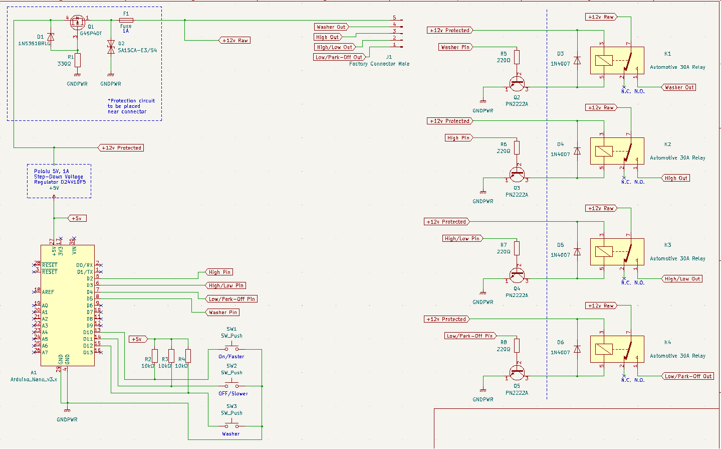
int ParkPin = 2;                    // Ground when @ Park
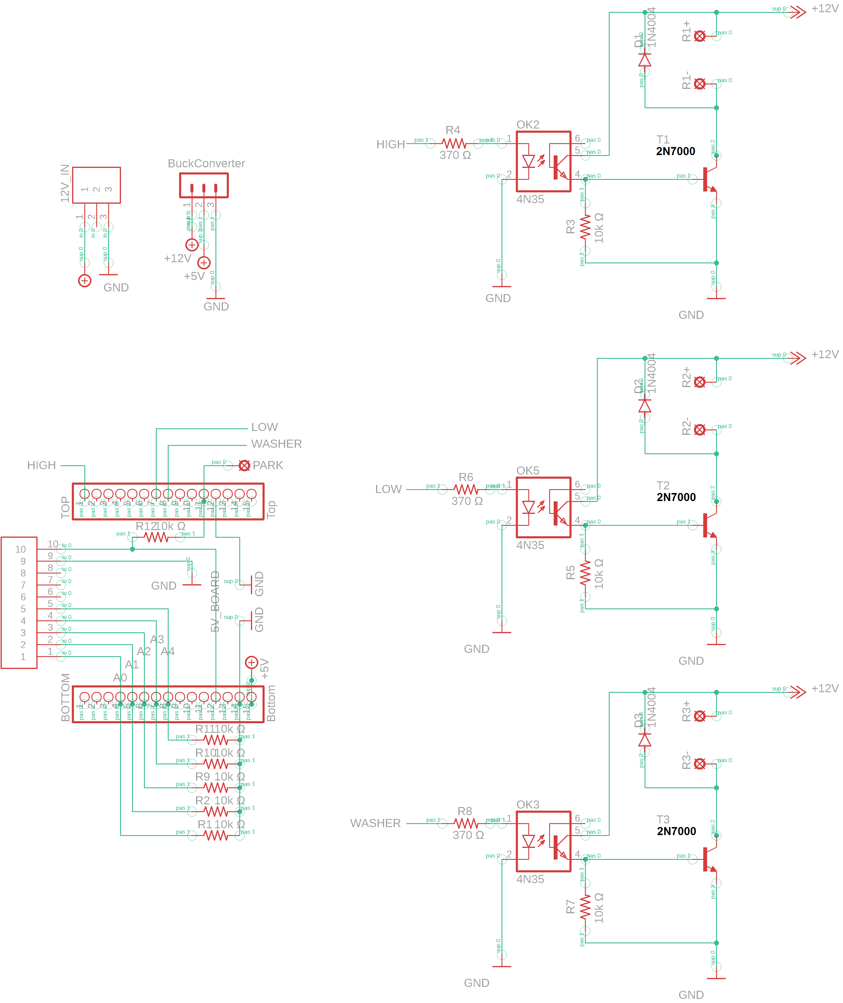
int HighPin = A1;                   // High Input - Circuit 92
int DelayPin = A0;                  // Input via different resistive values  - Circuit 93

// Defines Outputs
const int LowOutputPin =  12;       // LowSpeed out
const int HighOutputPin =  6;       // HighSpeed out
const int WasherOutputPin = 5;      // Washer Pump Out

int PosVal = 0;
int OldPosVal = 0;

int count = 0;        // Set count to zero
int LastCount = 0;    // To reset count back to zero

int D1 = 6500;        // 500 Delay approx 12 seconds with serial print on, 6500
int D2 = 5500;        // 400 Delay approx 9.5 seconds, 5500
int D3 = 4500;        // 300 Delay approx 7.5 seconds, 4400
int D4 = 3500;        // 200 Delay approx 4.75 seconds, 3500
int D5 = 1500;         // 100 Delay approx 2.5 seconds, 1500
int D6 = 80;         // Delay for code to wait before exiting case #
const int D7 = 50;          // Button Debounce press delay. Used cont int since it got rid of the warning below. code ran, just tried to get rid of warning
                                                            //warning: comparison between signed and unsigned integer expressions [-Wsign-compare]
                                                            //if(millis() - lastReading >= D7)
                                                            //   ~~~~~~~~~~~~~~~~~~~~~~~^~~~~


unsigned long previousMillis = 0;
unsigned long currentMillis;

int LowPin()                                                           // Value displayed with current resistors installed 957
{
  if (analogRead(DelayPin) >= 900 && analogRead(DelayPin) <= 970)   {  // Value displayed is 958
    return 1;
  }
  else   {
    return 0;
  }
}

int Highrequest()                      // Value displayed with current resistors installed 957
{
  if (analogRead(HighPin) >= 950 ) {   // Value displayed is 1023
    return 1;
  }
  else   {
    return 0;
  }
}

int WasherPin()                        // Value displayed with current resistors installed 1023
{
  if (analogRead(DelayPin) >= 1000) {  // && analogRead(DelayPin) <= 25)   {
    return 1;
  }
  else   {
    return 0;
  }
}

int DelaySpeed1()                      // Value displayed with current resistors installed 21 +/- 1
{
  if (analogRead(DelayPin) >= 18 && analogRead(DelayPin) <= 30)   {
    return 1;
  }
  else   {
    return 0;
  }
}

int DelaySpeed2()                      // Value displayed with current resistors installed approx 42 +/- 1
{
  if (analogRead(DelayPin) >= 35 && analogRead(DelayPin) <= 55)  {
    return 1;
  }
  else   {
    return 0;
  }
}

int DelaySpeed3()                      // Value displayed with current resistors installed approx 72 +/- 1
{
  if (analogRead(DelayPin) >= 65 && analogRead(DelayPin) <= 85)  {
    return 1;
  }
  else   {
    return 0;
  }
}

int DelaySpeed4()                      // Value displayed with current resistors installed approx 144 +/- 1
{
  if (analogRead(DelayPin) >= 130 && analogRead(DelayPin) <= 155)  {
    return 1;
  }
  else   {
    return 0;
  }
}

int DelaySpeed5()                      // Value displayed with current resistors installed  290 +/- 1
{
  if (analogRead(DelayPin) >= 260 && analogRead(DelayPin) <= 300)  {
    return 1;
  }
  else   {
    return 0;
  }
}

bool WasherState = 0;
bool ParkState = 0;
bool LowState = 0;
bool DelayState1 = 0;
bool DelayState2 = 0;
bool DelayState3 = 0;
bool DelayState4 = 0;
bool DelayState5 = 0;
bool HighState = 0;

void setup()

{
  Serial.begin(115200);
  debugln("+++++ Wiper Selection +++++");

  // Initialize the pins as an input:
  pinMode(ParkPin, INPUT_PULLUP);
  pinMode(HighPin, INPUT);
  pinMode(DelayPin, INPUT); 

  // Initialize the pins as an output:
  pinMode(LowOutputPin, OUTPUT);
  pinMode(HighOutputPin, OUTPUT);
  pinMode(WasherOutputPin, OUTPUT); 
   
}

 
void loop()

{
  static unsigned long lastReading = 0;
  if(millis() - lastReading >= D7)

  {
  lastReading = millis();

  ParkState = digitalRead(ParkPin);
  HighState = Highrequest();
  LowState = LowPin();
  WasherState = WasherPin();
  DelayState1 = DelaySpeed1();
  DelayState2 = DelaySpeed2();
  DelayState3 = DelaySpeed3();
  DelayState4 = DelaySpeed4();
  DelayState5 = DelaySpeed5();
  }
      
 PosVal = (!ParkState * 1) + (LowState * 2) + (HighState * 4) + (WasherState * 8) + (DelayState1 * 16) + (DelayState2 * 32) + (DelayState3 * 64) + (DelayState4 * 128) + (DelayState5 * 256);  // calculate Position selected
  if (PosVal != OldPosVal)  
  {
    debugln();
    debug ("Park Signal = ");
    debug (ParkState);
    debug ("  Low Signal = ");
    debug (LowState);
    debug ("  High Signal = ");
    debug (HighState);
    debug ("  Washer Signal = ");
    debugln(WasherState);
    debug ("DelaySpeed1 = ");
    debug (DelaySpeed1());
    debug ("  DelaySpeed2 = ");
    debug (DelaySpeed2());
    debug ("  DelaySpeed3 = ");
    debug (DelaySpeed3());
    debug ("  DelaySpeed4 = ");
    debug (DelaySpeed4());
    debug ("  DelaySpeed5 = ");
    debug (DelaySpeed5());
    debug ("  PosVal # ");
    debugln(PosVal);
    debug  ("Count @ ");  
    debugln (count);
    debug ("A0 Signal value @ ");
    debugln(analogRead(DelayPin));
    debug ("A2 High value @ ");
    debugln(Highrequest());    

    switch (PosVal)
    {
      case 1:
        count = LastCount;                            // Resets count value for next cycle
        debugln("OFF Selected");
        digitalWrite(LowOutputPin, HIGH);             // Continue movement till ParkPin is grounded
        digitalWrite(HighOutputPin, LOW);
        digitalWrite(WasherOutputPin, LOW);
        break;
              
      case 0:
        count = LastCount;                            // Resets count value for next cycle
        debugln("PARK Selected");                     //Switch turned to Off and Wiper Motor ParkPin grounded
        digitalWrite(LowOutputPin, LOW);
        digitalWrite(HighOutputPin, LOW);
        digitalWrite(WasherOutputPin, LOW);
        break;

        
//     default:
//      debugln("Invalid Selection");
//      digitalWrite(LowOutputPin, LOW);
//      digitalWrite(HighOutputPin, LOW);
      break;
    }
  }
    OldPosVal = PosVal;  

}

More trouble shooting, Pin 12 is the one that is activating for a split second on boot-up.
Pin12 will also activate for the same split second when serial monitor window is opened.

I swapped:

// Defines Outputs
const int LowOutputPin =  12;       // LowSpeed out
const int HighOutputPin =  6;       // HighSpeed out
const int WasherOutputPin = 5;      // Washer Pump Out

to

// Defines Outputs
const int LowOutputPin =  6;       // LowSpeed out
const int HighOutputPin =  12;       // HighSpeed out
const int WasherOutputPin = 5;      // Washer Pump Out

to see if the position of output is effected, The first output is pin6, then pin12 and pin12 is the one that flashed... so order of outputs doesnt effect it.

when prototyping the board on the Uno rev3, pin 13 did something similar on startup, so I used a different pin.. Maybe pin12 is not a good output pin.

Also tested on a genuine Nano, exact same results.

When the opto transistor turns ON, you will blow up the Opto and 2N2222
:scream:

T2 needs a base resistor or add a collector resistor to the Opto.

sorry, 2n7000, I missed that when updating the parts list ... let me update the name ... sorry

That’s quite a difference :sunglasses:

1 Like

also took the M off of the 4N35.. not sure but what M sands for, but it was the right shape and had the same pins... and i went for it on the schematic. It worked for the pcb board ecept the pins were further out than expected.... it soldered together fine in the end.

Please use the correct symbol for the 2N7000.

image

The base eagle library doesnt have one, I will search for it shortly , v3 of a quick mspaint fix
(edit: added more library's, still no 2n7000, found one that has the same schematic, and same footprint as the part I have. All legs of the 2n7000 are strait close together, not the outer legs offset)

video showing pin 12 going high on startup

the all the lights flicker a little, but pin 12, is the one that is brighter on startup (it is the one that I activate at the end of the video with push button
When relay harness is connected, inplace of this led connector, only pin12 clicks.

progress :slight_smile: with the dreaded delay... trying anything I could find online... I will try and change it to millis() later

void setup()

{
  Serial.begin(115200);
  debugln("+++++ Wiper Selection +++++");
  
  delay(200);


Led strips still have the dim split second on then off but Pin 12 was not full bright like before. I swapped LED connector for relay harness and no more boot up relay activation.

Not sure if this is the right way to go about it? I will play with this again tomorrow, and try and get millis() inplace of delay (200)