OPTREX DMC40457 don't work

Hi,

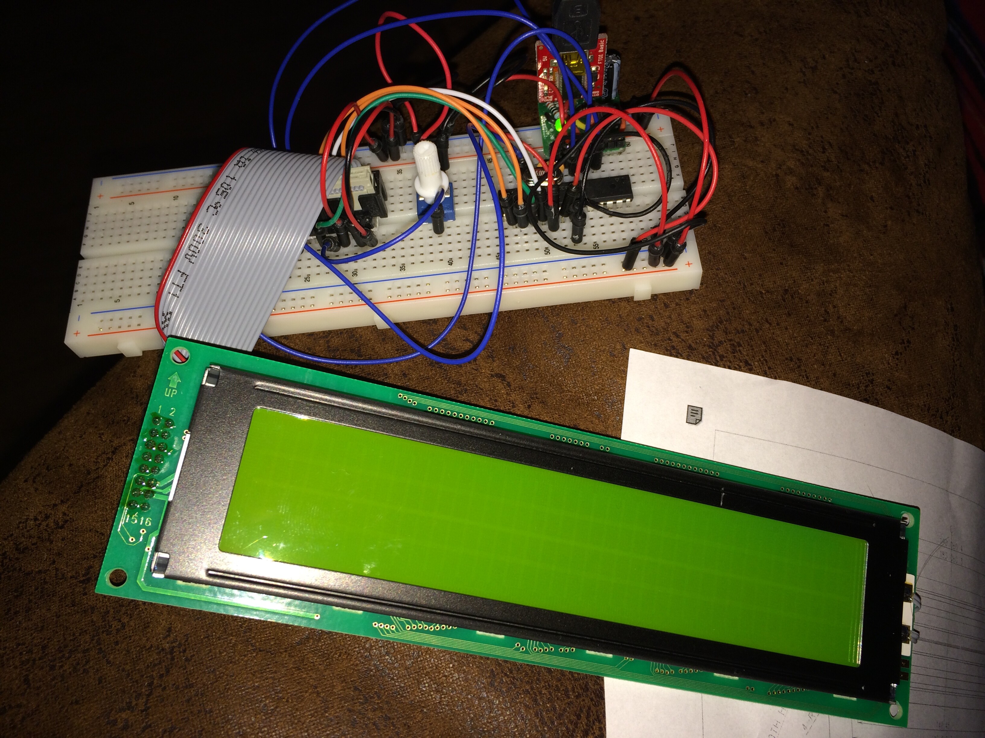
who can help me with my ' OPTREX DMC40457'?

I use the following code:

#include <LiquidCrystal.h>

LiquidCrystal lcd(13,12,11,10,5,4,3,2); //RS, RW, E2, E1, D4, D5, D6, D7

void setup() {
  lcd.begin(40,4);
  lcd.setCursor(0,0);
  lcd.print("Eing.:1 = 0");
  lcd.setCursor(0,1);
  lcd.print("Eing.:2 = 0");
  lcd.setCursor(0,2);
  lcd.print("Eing.:3 = 0");
  lcd.setCursor(0,3);
  lcd.print("Eing.:4 = 0");
  lcd.setCursor(12,0);
  lcd.print("|");
  lcd.setCursor(12,1);
  lcd.print("|");
  lcd.setCursor(12,2);
  lcd.print("|");
  lcd.setCursor(12,3);
  lcd.print("|");
  lcd.setCursor(14,0);
  lcd.print("Eing.:5 = 0");
  lcd.setCursor(14,1);
  lcd.print("Eing.:6 = 0");
  lcd.setCursor(14,2);
  lcd.print("Eing.:7 = 0");
  lcd.setCursor(14,3);
  lcd.print("Eing.:8 = 0");
  lcd.setCursor(26,0);
  lcd.print("|");
  lcd.setCursor(26,1);
  lcd.print("|");
  lcd.setCursor(26,2);
  lcd.print("|");
  lcd.setCursor(26,3);
  lcd.print("|");
  lcd.setCursor(28,0);
  lcd.print("Eing.:9 = 0");
  lcd.setCursor(28,1);
  lcd.print("Eing.:10= 0");
  lcd.setCursor(28,2);
  lcd.print("Eing.:11= 0");
  lcd.setCursor(28,3);
  lcd.print("Eing.:12= 0");
}

void loop() {
}

And I use this library: Google Code Archive - Long-term storage for Google Code Project Hosting. LiquidCrystal1.0.zip

The code compiles and upload well, only nothing happened. :astonished: :~

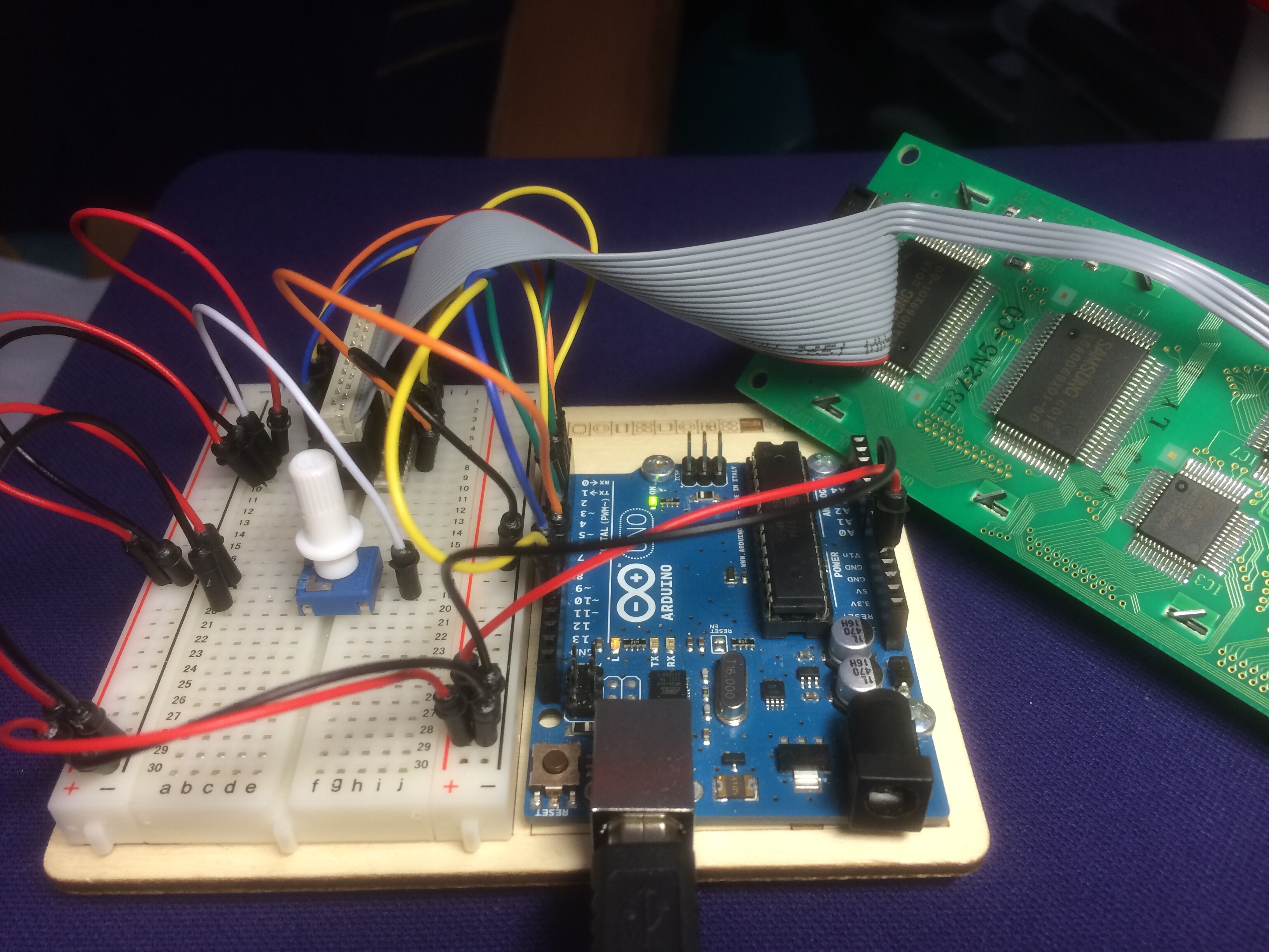
I use the Arduino 1.5.5 and the 1.0.5 IDE on a OSX. whit a bare bone ATmega328p/Ext:16Mhz

 LiquidCrystal lcd(13,12,11,10,5,4,3,2); //RS, RW, E2, E1, D4, D5, D6, D7

Did this constructor come from the Library ?

Edwin:

I know for a fact that this library is properly written, following all of the Hitachi recommendations. When John was developing the program he plugged his display directly into the socket on the end of his Mega so there were no wiring issues.

On the other hand you are using a ribbon cable and then jumpers to get to the pins on your breadboarded processor so there are several possibilities that come to mind.

You will have to first verify that your processor itself is wired properly. I see one capacitor near your crystal but most crystals require two. There should be a decoupling capacitor between each power pin and GND as well. These should be as close to the IC as you can get them.

You will also have to verify that your data and control lines for the LCD go to the pins that you have specified in your constructor. Normally we can help with this if we have a good photograph, but the ribbon cable makes it difficult.

Some of my Optrex LCDs require a negative voltage for the contrast pin but the data sheet seems to verify that yours will work with a small positive voltage on pin 3 as long as you are running the LCD with 5 volts on pin 2.

Don

Hi Don,

Sorry for the late response. But thanks for your comment. Here are some detailed pictures.
The ATmega328PU works well.
All the wires are also good and also the breadboard. My idea is that the pinout is wrong?

DMC-40457N.pdf (226 KB)

The ATmega328PU works well.

It may seem to "work well" as is, but without any decoupling capacitors you really don't know. This is especially true when you start operating another microprocessor ( the LCD controller) nearby especially when it is powered by the same supply.

My idea is that the pinout is wrong?

Here is my start at attempting to troubleshoot your wiring. It would help to know more about the ribbon cable.

LCD         Arduino     ATMega328  Ribbon
11  RS      13          PB5  19
10  RW      12          PB4  18
15  E2      11          PB3  15
 9  E1      10          PB2  16
 4  D4       5          PD5  11
 3  D5       4          PD4   6
 2  D6       3          PD3   5
 1  D7       2          PD2   4

Don

Now I got it connected to my Arduino Uno.

I think I have the wrong data sheet.
My LCD has the "Samsung S6A0069X01" chip's and not the "HD44780".

My LCD has the "Samsung S6A0069X01" chip's and not the "HD44780".

The S6A0069 is an HD44780 compatible controller. The X01 most likely refers to 'ROM version' which specifies the particular character set in the chip.

Don