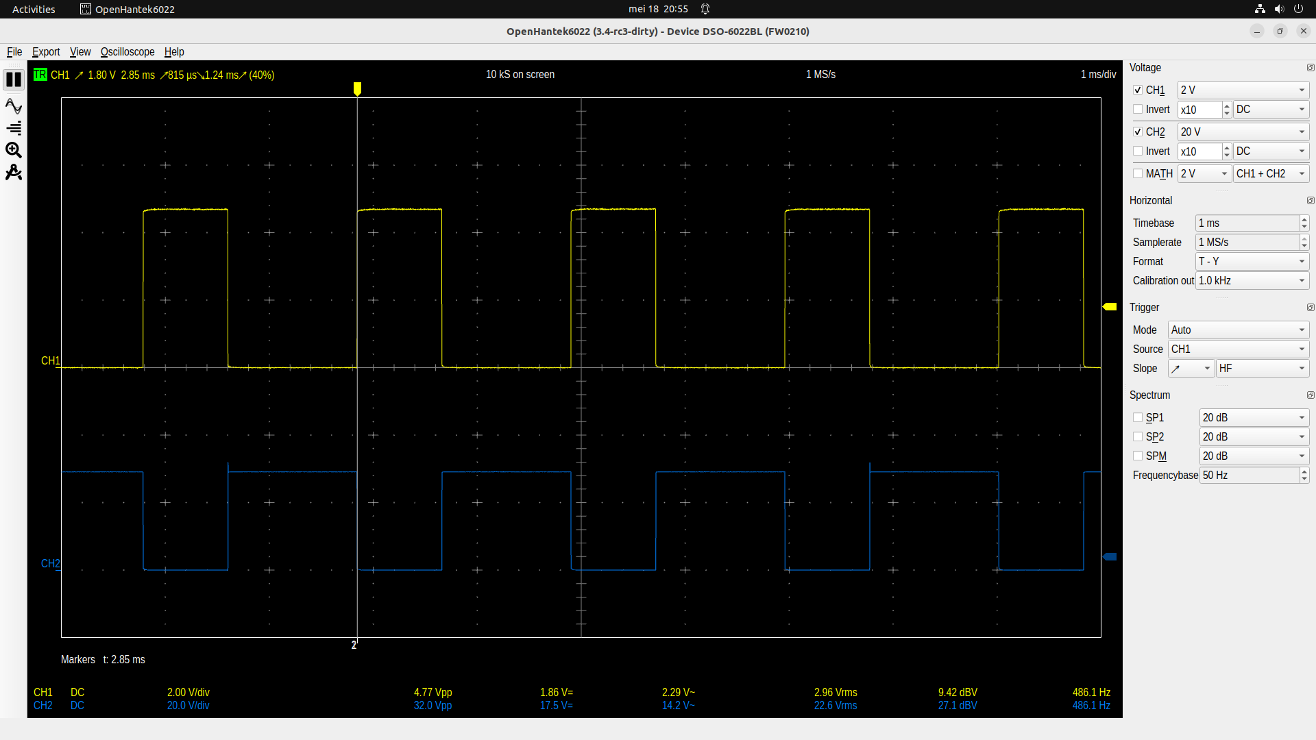
The yellow square wave comes from a arduino meg 2560 pin 5
The blue wave is measured on TIP120 over collector and emitor.
The blue wave should be a nice inverted wave of the yellow wave.
But the blue wave is a mess.
Why should a square wave connected to the inductance of the motor produce a nice inverted yellow wave? Change the motor to an incandescent automobile light bulb an test again.
The sine part, but the flat part after the sine to ?
Surprises me this part is so exactly flat.
This example with a arduino and a TIP120 is several times give on the internet.
But to me, it seems not to work.
Very strange.
Apparently i do not understand it
The ringing observed when Pin 5 is LOW appears to have a frequency on the order 10 kHz; if the motor inductance is on the order of a millihenry, this would suggest the resonance is created by coupling to a microfarad-scale capacitance. That is much larger than the diode or transistor capacitances, so perhaps something in the power supply.
No, it will never be an inverted yellow line. If the yellow line is at Gnd, the TIP120 is switched off - high impedance. So what you are measuring is the back EMF of the motor. Between pulses, the motor acts like an unloaded generator. It looks a bit weird because you are measuring the voltage across the transistor and not the voltage across the motor. The motor voltage is the difference between the blue line and the 12V supply.
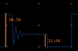
There may be a small amount of back-EMF contributing to the measured signal, but as shown in the annotated oscilloscope trace below, after the ringing has subsided, the back-EMF appears to be no more than 0.4 V (assuming that the "12-V" power supply does produce 12.0 V).
On the other hand, the initial 30-V spike is unrelated to back-EMF — this is caused by the inductive spike resulting from the abrupt change in flux linkage in the armature coil.
I admit I didn't look close enough to the scope settings. But they don't make any sense if its a 12V supply.
If the transistor is in high impedance state you definitely can measure the generated voltage of the motor. It can even be used to regulate the engine speed in a control circuit. I did this already many years ago (with pure HW and without a microcontroller ).
My point was that the back-EMF is going to be smaller than the driving voltage, so the collector-emitter voltage difference initial part of the response should be lower than 12V, unless the motor is reversing direction. The much larger voltage pulse seen in the oscilloscope trace therefore would not be explainable by back-EMF, unless OP is not telling is the full story (which the resistor test suggests is the case).
The top of the blue line is 30 volt which is the power supply..
There is no 12 volt power supply.
The second blue horizontal line voltage varies, depending on the pulse width of the yellow line.
I can not find a way to show a screencast video here.
Then you could see how the second horizontal blue line varies.
The fact it is now 12 volt is purely a coincident.
The diagram also shows that the TIP120 base is controlled by pin 2, not pin 5 as you stated, and the diagram shows an Arduino Nano, not a Mega 2560. The original diagram also depicts a solenoid, not a DC motor...
What else is different in your circuit compared to the original circuit (which evidently dates back to 2013)?