I noticed some missing PROGMEM statements. Maybe this will work now:
The before and after are both untested.
I noticed some missing PROGMEM statements. Maybe this will work now:
The before and after are both untested.
I knew i will get it. Finally here is nice one with 115200 baud rate!!!!!!!!!!!!!!!!

first of all thanks to you all! for the last few days i was messing with OV7670 without FIFO.. now able to burn your arduino code directly from arduino IDE . but having problem in framegrabber codes and it gives error like in MinGw,
sir kindly help me out.
on the arduino side i am using
camtest.ino (21.1 KB)
Finally managed to start OV7670 on Arduino Pro Micro with Wire library.
At least I'm getting some data when XCLK is set to PWM and not getting it when it's not.
Hooked it up using just 3 wires and pullup resistors, as here:
Frankly it works fine without pullup, but it needs 3.3v, I used level converter. Currently looks like this:
I managed to read the wire but it's mostly zeros, some 0x73 in the beginning and random data.
Could anyone explain in layman's terms how to read the frame properly?
Specs and the first post are unreadable. Default camera settings are OK.
Is it even possible to read frame data, using just 3 wires, without using D0-D7?
My sketch:
// Last updated version at http://pastebin.com/GcT3gnmw

#include <Wire.h>

/*   Arduino Pro Mini (3.3v) vs OV7670:

  VCC  - 3V3
  GND  - GND
  SIOD - 2
  SIOC - 3
  XCLK - 9

*/

uint8_t sensor_addr = 0x42;

uint8_t rdReg(uint8_t reg) {
  Wire.write(reg & 0x00FF);
  Wire.endTransmission();
  Wire.requestFrom((sensor_addr >> 1), 1);
  if (Wire.available()) {
    return Wire.read();
    delay(1);
  } else {
    return 0;
  }
}

uint8_t wrReg(uint8_t reg, uint8_t dat){
  Wire.beginTransmission(sensor_addr >> 1);
  Wire.write(reg & 0x00FF);
  Wire.write(dat & 0x00FF);
  byte result = Wire.endTransmission();
  delay(1);
  return result;
}


void setup() {
  pinMode(9, OUTPUT);

  //Generating 8MHZ PWM on pin9
  TCCR1B |= (1 << CS10);  //selecting prescaler 0b001 (Tclk/1)
  TCCR1B &= ~((1 << CS12) | (1 << CS11)); // turn off CS12 and CS11 bits
  TCCR1A |= ((1 << WGM11) | (1 << WGM10)); //Configure timer 1 for TOP mode (with TOP = OCR1A)
  TCCR1B |= ((1 << WGM13) | (1 << WGM12));
  TCCR1A |= (1 << COM1A0); // Enable timer 1 Compare Output channel A in toggle mode
  TCCR1A &= ~(1 << COM1A1);
  TCNT1 = 0;
  OCR1A = 0; //for 8MHz: 0, for 10kHz: 799

  Wire.begin();

  // start
  Wire.beginTransmission(sensor_addr >> 1);
  Wire.write(0x01 & 0x00FF);
  Wire.endTransmission();

  // init serial
  Serial.begin(115200); // hc-05 works at 115200
  delay(2000);
}

void captureImg() {
  // read from page 0
  Wire.beginTransmission(sensor_addr >> 1);
  Wire.write(0x0B & 0x00FF);
  if (Wire.endTransmission()!=0) {
    return;
  }

  for (unsigned long i = 0; i < 65535; i++) {
    Wire.requestFrom(sensor_addr >> 1, 1);
    if (Wire.available()) {
      Serial.write(Wire.read());
    }
  }
}

void loop() {
  if (Serial.available()) {
      captureImg();
  }
}
Figures I2C is just for settings. For pixel data I have to read D0-D7 and sync with HREF, VSYNC and PCLK.
Managed to actually capture something. Not much, but it changes with lighting.
The FPS is gnarly, roughly 2 frames a second for a qqvga frame.
Probably not enough speed with digitalRead. And synchronization is incomplete.
Sketch: ov7670-wire.ino - Pastebin.com
Viewer: cppgrabber.cpp - Pastebin.com
Replaced the digitalRead code with bit shifting with this:
void captureImg() {
  // PIND is 0..7, PINB is 8..13, PINC is A0..A5 (e.g. pin 10 would be PINB & 4)
  const int w = 320;
  const int h = 240/4;
  unsigned char buf[w*2];

  while (digitalRead(VSYNC) == LOW);
  while (digitalRead(VSYNC) == HIGH);
  for (int y = 0; y < h; y++) {
    for (int x = 0; x < w; x++) {
      while (digitalRead(PCLK) == HIGH);
      buf[x] = (PINC & 15) | (PIND & 240); // pins A0..A3 and 4..7 (PINC & 00001111, PIND & 11110000)
      //while (digitalRead(PCLK) == LOW);
      //while (digitalRead(PCLK) == HIGH);
      //while (digitalRead(PCLK) == LOW);
    }
    Serial.write(buf, w);
  }
}
Getting something that loosely resembles the picture:
Can't write directly to the UART (UDR0) on Arduino Pro Micro because there's apparently no support for that (USB data were received/send via FIFO in RAM --> there's no 'register' for sending/receiving data). So the code for USB would look (and work) differently. Frankly I'm leaning towards Pro Mini, Pro Micro seems unnecessary expensive and has less GPIOs.
I tried to connect Arduino Due and ov7670 since Mega doesn't give much difference with Uno.
You can find my results at Arduino Due and OV7670
Well, just like everyone else here, I'm having trouble with my unbuffered OV7670 (specifically the one Arducam sells on amazon). I've been using this tutorial:
I've gotten the SCCB working correctly, and I'm able to capture image data (I'm using the default YCbCr4:2:2 format for now), but no matter what I do the image is always near-black (Y values below 5 and Cb and Cr values around 128). The image does get slightly brighter (Y values around 30) if I put a flashlight directly against the sensor. I've tried changing the "AGC" values, but it only made the image very slightly brighter. Furthermore, the images all appear to be random static, but this is probably just noise since they're all so dark.
I'm guessing I have to change some registers somewhere, but I don't know which ones. Does anyone know which registers I should be poking at?
It could also be a problem with Arducam's module. I don't think my hardware is broken since I bought 2 and they both behave exactly the same. Can anyone confirm that Arducam's unbuffered OV7670 works, and if not can someone post a specific retail link to a module that they have personally confirmed does work?
Nevermind, I found the problem. Turns out the minimum frequency in the datasheet is a bit more than a suggestion. The embedded logic all works fine with XCLK frequencies lower than 10 MHz, but the light sensors don't.
In case anyone was wondering how I figured that out by the way, I used register 0x06 to check the average amount of light being detected by the camera even though I was having trouble capturing full images at high frequency. If there is no light hitting the sensor then that value should be 0, and at ambient room light levels I found it varied from 0x06 to 0x07.
Hello, I have a problem with the sharpness in the cam. I use the code of "GitHub - ComputerNerd/ov7670-no-ram-arduino-uno: Allows you to use a non fifo ov7670 on the arudino uno without external spi ram like other examples. Sends the data to UART.". May the problem be some registers? Thank you. Sorry my english, but i dont speak english very well.
This picture was taken in QQVGA YUV (black and white, first byte)
I use arduino mega with the clock generator:
DDRL |= (1 << 3);//pin 46
ASSR &= ~(_BV(EXCLK) | _BV(AS2));
//generate 8mhz clock
TCCR5A =67;
TCCR5B=17;
hi evry body.im biginner and i dont know how to connect ov7670(18 pins) to arduino uno r3.
plz help me...
i want save picture in SD card or send it to web page or save in arduno...
Hi all,
Can anyone help me integrate OV7670 Camera Module with Raspberrypi3...
Please guys it's urgent I need help regarding this....
Thank you.
I got the Communications working.
I used the resistors pullup, and splitter.

I see continuous Data coming out of Arduino and Cam at 1M baud.
But, I am not sure how to convert the Data.
If I cover the lens with my hand, I receive Low values, like 0A 0A 0A 0A 09 09 etc.
If I point the Cam across the room, I receive assorted l\lines of Mid and High values, such as:
7C 7A 78 75 75 75 7E 76 73 74 76 74 74 7E 71 74
74 76 77 77 7D 77 79 79 7B 7E 7D 7D 7D 7E 7D 09
7E 7E 7E 7E 7D 6D 59 7E 45 3C 39 39 38 35 31 28
24 27 2C 31 35 35 36 35 34 32 31 31 30 2F 2F 2D
2D 2D 2D 2C 2B 2A 2A 28 29 27 27 27 27 27 27 28
28 28 28 27 28 28 28 28 27 26 25 25 24 25 23 7E
22 21 20 21 22 22 23 22 21 20 7E 20 22 22 22 23
23 23 24 25 23 21 26 42 09 5F 7E 70 0A 68 75 47
2A 79 0A 44 7D D9 78 FB FF 76 FF FE FE FF FF FF
FD FD 7D FF FF 7E FB F7 7A FC FD 77 FA FA 7C 7D
42 3F 47 50 5C 66 70 7A 79 7B 77 0A 78 75 76 74
77 73 75 A0 74 A2 73 A5 72 A6 70 A6 72 A9 74 AC
74 AF 76 B4 72 B5 72 B8 73 BD 72 C2 70 C5 73 C5
6D C6 74 CB 72 CB 70 CD 6E C9 6D C0 6E B8 6B B0
I then dropped it into 16bit BMP files 320x240 and 240x320.
But all I see is garbage (with some twists maybe).
The Images attached are BMP just with TXT suffix to attach here - just change to BMP.
I attached 1 image as JPG for viewing.

I understad BMP Header Images.
What is the Color Bit scheme received from the Cam/Arduino of QVGA 320x240 YUV422 ?
-How is this 2 bytes per Color ?
ov7670_no_ram_arduino_uno_camera_ss.ino (27.2 KB)
_Ard_ov7670_cam_20160918_1M_320x240_04_Light_Dark_light_Dark_PIEC_04-01.bmp.txt (100 KB)
_Ard_ov7670_cam_20160918_1M_240x320_04_Light_Dark_light_Dark_PIEC_04-02.bmp.txt (100 KB)
_Ard_ov7670_cam_20160918_1M_320x240_005_PIEC_05-01.bmp.txt (37.6 KB)
_Ard_ov7670_cam_20160918_1M_320x240_005_PIEC_05-01.bmp.txt (37.6 KB)
Can I just use this ? :
B = 1.164(Y - 16) + 2.018(U - 128)
G = 1.164(Y - 16) - 0.813(V - 128) - 0.391(U - 128)
R = 1.164(Y - 16) + 1.596(V - 128)
Reference:
http://www.fourcc.org/fccyvrgb.php
This seems to better describe it:
YUV422 looks like YUYV, where this is definition for 2 pixels, so it become Y0 U0 Y1 V0, where Y0U0V0 is for pixel1 and Y1U0V0 for pixel2.
Convert from YUV to RGB :
// YUV422 :
Y = pixel1;
U = pixel2;
Y1 = pixel3;
V = pixel4;
R = Y + 1.4075 * (V - 128);
G = Y - 0.3455 * (U - 128) - (0.7169 * (V - 128));
B = Y + 1.7790 * (U - 128);
fill(R, G, B);
rect(x2, y, 1, 1); // draw first pixel
R = Y1 + 1.4075 * (V - 128);
G = Y1 - 0.3455 * (U - 128) - (0.7169 * (V - 128));
B = Y1 + 1.7790 * (U - 128);
fill(R, G, B);
rect(x2+1, y, 1, 1); // draw second pixel
So: 7A 7B A1 78 A7 7C AB 76 would be:
Y0 = 7A , U=7B , Y1=A1 , V=78
I decided to whip up a quick Script in Cygwin to convert one of the files:
cat /tmp/data06.txt
sed s/" "/\n" "/g |
awk '
BEGIN{CNT=0;print("");} ;
{
/* Y0 U Y1 V : */
CNT ++;
if(CNT==1) { Y0=strtonum( "0x"$1 ); /print("1: "Y0);/ }
if(CNT==2) { U=strtonum( "0x"$1 ); /print("2: "U);/ }
if(CNT==3) { Y1=strtonum( "0x"$1 ); /print("3: "Y1);/ }
if(CNT==4) {
CNT=0;
V=strtonum( "0x" $1 );
R0 = Y0 + 1.4075 * (V - 128);
if(R0 < 0) R0=0;
if(R0 > 255) R0=255;
G0 = Y0 - (0.3455 * (U - 128)) - (0.7169 * (V - 128));
if(G0 < 0) G0=0;
if(G0 > 255) G0=255;
B0 = Y0 + (1.7790 * (U - 128));
if(B0 < 0) B0=0;
if(B0 > 255) B0=255;
R1 = Y1 + 1.4075 * (V - 128);
if(R1 < 0) R1=0;
if(R1 > 255) R1=255;
G1 = Y1 - (0.3455 * (U - 128)) - (0.7169 * (V - 128));
if(G1 < 0) G1=0;
if(G1 > 255) G1=255;
B1 = Y1 + (1.7790 * (U - 128));
if(B1 < 0) B1=0;
if(B1 > 255) B1=255;
/printf("4: %x %x %x %x \n",Y0,U,Y1,V );/
/printf("%02X %02X %02X %02X %02X %02X %02X %02X \n", R0,G0,B0,00, R1,G1,B1,00);/
printf("%02X %02X %02X %02X %02X %02X \n", B0,G0,R0, B1,G1,R1);
}
/print strtonum( $1 )/
} '
data06bmp.txt
Attached:
data06.txt - 1 Snapshot (I used text "CAMERA *" to mark Image start/end) in Hex as Yuv422 format
data06bmp.txt - converted to BGR format
_Ard_ov7670_cam_20160918_1M_240x320_24b_006_PIEC_06-04.bmp.txt - is dropped into BMP 24bit file (3 bytes per pixel)
..JPG - to view here.

Looks ugly until you realize that it looks like the Lens - probably out of Focus ...
data06.txt (450 KB)
data06bmp.txt (788 KB)
_Ard_ov7670_cam_20160918_1M_240x320_24b_006_PIEC_06-04.bmp.txt (225 KB)
Okay,
New Snapshot, focused out 1 or 2 Lens rotations:
First, looks wierd, but I used 240x320 - backwards.

Second, is Sideways - I guess the Bus is Verticle - not Horiz:

Third, Snapshot aligned- of the children's craft shelf:

Fourth, RGB (not BGR as BMP 24bit specifies on internet):
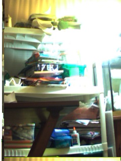
Success !
Updated Script (with RGB fix) for Linux/Cygwin :
cat /tmp/data07.txt |
sed s/" "/\n" "/g |
awk '
BEGIN{CNT=0;print("");} ;
{
/* Y0 U Y1 V : */
CNT ++;
if(CNT==1) { Y0=strtonum( "0x"$1 ); /print("1: "Y0);/ }
if(CNT==2) { U=strtonum( "0x"$1 ); /print("2: "U);/ }
if(CNT==3) { Y1=strtonum( "0x"$1 ); /print("3: "Y1);/ }
if(CNT==4) {
CNT=0;
V=strtonum( "0x" $1 );
R0 = Y0 + 1.4075 * (V - 128);
if(R0 < 0) R0=0;
if(R0 > 255) R0=255;
G0 = Y0 - (0.3455 * (U - 128)) - (0.7169 * (V - 128));
if(G0 < 0) G0=0;
if(G0 > 255) G0=255;
B0 = Y0 + (1.7790 * (U - 128));
if(B0 < 0) B0=0;
if(B0 > 255) B0=255;
R1 = Y1 + 1.4075 * (V - 128);
if(R1 < 0) R1=0;
if(R1 > 255) R1=255;
G1 = Y1 - (0.3455 * (U - 128)) - (0.7169 * (V - 128));
if(G1 < 0) G1=0;
if(G1 > 255) G1=255;
B1 = Y1 + (1.7790 * (U - 128));
if(B1 < 0) B1=0;
if(B1 > 255) B1=255;
/printf("4: %x %x %x %x \n",Y0,U,Y1,V );/
/printf("%02X %02X %02X %02X %02X %02X %02X %02X \n", R0,G0,B0,00, R1,G1,B1,00);/
/printf("%02X %02X %02X %02X %02X %02X \n", B0,G0,R0, B1,G1,R1);/
printf("%02X %02X %02X %02X %02X %02X \n", R0,G0,B0, R1,G1,B1);
}
/print strtonum( $1 )/
} ' >
data07bmp.txt
Some hints in the Image Downloading and Conversion:
After converting Data from Yuv422 (4bytes per 2pixels) to RGB (6bytes as 2 pixels) ,
If Image is garbage with Horizontal Segments
=> then Image maybe be saved Wrong as 240x320 - should be 320x240
If Image is All PINK
=> Yuv422 data is missaligned/missing (1 or 3) bytes
If Image is All CYANA
=> Yuv422 data is missaligned/missing (2) bytes
Mr Arduino,
Would it be useful to Input and Check the HREF/HSYNC to the Arduino,
to verify that the Pixels are not missaligned per Line.
Then, Fix/Realign the Pixel Bytes if missaligned at the start of a new HLine.
I think that this could reduce Image losses to Line losses.
Of course, there may be losses from high Baudrate (1M) - possibly reducing it may also help.


