Override Arduino code with an RC signal

I have a simple RC receiver, transmitter, an Arduino Mega, and an S51 servo.

I want to write my own code to control my servo, but if I send a signal from the transmitter, I want the RC transmitter to override anything that is happening in the code.

I cannot seem to find a single example of this override online. This should be very easy.

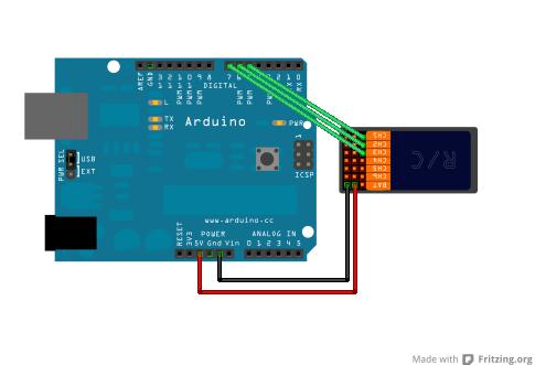
So far I connected the servo to the RC receiver and the receiver to the Arduino Mega and I am able to control it through the RC transmitter.

// First Example in a series of posts illustrating reading an RC Receiver with
// micro controller interrupts.
//
// Subsequent posts will provide enhancements required for real world operation
// in high speed applications with multiple inputs.
//
// http://rcarduino.blogspot.com/
//
// Posts in the series will be titled - How To Read an RC Receiver With A Microcontroller

// See also http://rcarduino.blogspot.co.uk/2012/04/how-to-read-multiple-rc-channels-draft.html

#define THROTTLE_SIGNAL_IN 0 // INTERRUPT 0 = DIGITAL PIN 2 - use the interrupt number in attachInterrupt
#define THROTTLE_SIGNAL_IN_PIN 2 // INTERRUPT 0 = DIGITAL PIN 2 - use the PIN number in digitalRead

#define NEUTRAL_THROTTLE 1500 // this is the duration in microseconds of neutral throttle on an electric RC Car
volatile int val;

volatile int nThrottleIn = NEUTRAL_THROTTLE; // volatile, we set this in the Interrupt and read it in loop so it must be declared volatile
volatile unsigned long ulStartPeriod = 0; // set in the interrupt
volatile boolean bNewThrottleSignal = false; // set in the interrupt and read in the loop
// we could use nThrottleIn = 0 in loop instead of a separate variable, but using bNewThrottleSignal to indicate we have a new signal
// is clearer for this first example

#include <Servo.h>
Servo servo;
#define SERVO_PIN 3

void setup()
{
  // tell the Arduino we want the function calcInput to be called whenever INT0 (digital pin 2) changes from HIGH to LOW or LOW to HIGH
  // catching these changes will allow us to calculate how long the input pulse is
  attachInterrupt(THROTTLE_SIGNAL_IN, calcInput, CHANGE);
  servo.attach(SERVO_PIN);
  Serial.begin(9600);
}

void loop()
{
  // if a new throttle signal has been measured, lets print the value to serial, if not our code could carry on with some other processing
  if (bNewThrottleSignal)
  {

    //val = map(nThrottleIn, 1092, 1928, 0, 180);
    Serial.println(nThrottleIn);
    delay(100);
    //servo.write(val);

    // set this back to false when we have finished
    // with nThrottleIn, while true, calcInput will not update
    // nThrottleIn
    bNewThrottleSignal = false;
  }

   else {
    Serial.println("Bla bla bla, we are here because the transmitter is not on");
    delay(100);
   }
  
}


void calcInput()
{
  // if the pin is high, its the start of an interrupt
  if (digitalRead(THROTTLE_SIGNAL_IN_PIN) == HIGH)
  {
    // get the time using micros - when our code gets really busy this will become inaccurate, but for the current application its
    // easy to understand and works very well
    ulStartPeriod = micros();
  }
  else
  {
    // if the pin is low, its the falling edge of the pulse so now we can calculate the pulse duration by subtracting the
    // start time ulStartPeriod from the current time returned by micros()
    if (ulStartPeriod && (bNewThrottleSignal == false))
    {
      nThrottleIn = (int)(micros() - ulStartPeriod);
      ulStartPeriod = 0;

      // tell loop we have a new signal on the throttle channel
      // we will not update nThrottleIn until loop sets
      // bNewThrottleSignal back to false
      bNewThrottleSignal = true;
    }
  }
}

Your post was MOVED to its current location as it is more suitable.

Could you also take a few moments to Learn How To Use The Forum.

Other general help and troubleshooting advice can be found here.
It will help you get the best out of the forum in the future.

It is unclear, is the servo connected to the Mega? Post a schematic.

How is the servo powered? If with an external supply (recommended) is the external supply ground connected to Arduino ground?

Remeber that in a conventional RC setup the transmitter is constantly sending a signal to the receivers servo, even if the joystick does not move.

You can do this if you read the signals from the RC receiver on the Mega and pass them on to the servo. Search the forum for posts by JohnRedEarth. He posted some code that did this that he was using to control an RC U-boat. He wanted to command an emergency surface if he lost signal.

You can use the same thing to share command of the servo, although as srnet implies, you'll need to figure out when to ignore the same old signals you're getting when the RC controller is still.

Ok, what if I want the code to be overwritten if I turn on the transmitter?

I have something very similar to this except that its connected to the digital inputs on the Mega.

Sketch image

The servo is powered through the radio receiver.

could you use a hardware circuit that selects where the RC pulse comes from and which selects the RF source if it is present? or use the arduino to determine if the RF source is active and selects the source?

Can you elaborate on this hardware circuit?

Can you explain why you want to do this ?

a two-input multiplexer would selectively pass one of two binary signals to a common output

I uploaded the code Ive been using.

If I turn on the transmitter I get the following output:

Bla bla bla, we are here because the transmitter is not on
1508
Bla bla bla, we are here because the transmitter is not on
1512
Bla bla bla, we are here because the transmitter is not on
1512
Bla bla bla, we are here because the transmitter is not on
1512

and then if I turn off the transmitter, I get the same output as above.

Why is it printing both statements in the if and else? It should only print one of them.

Hi Maria,

I've worked with high-performance radio controlled helicopters a lot (each one has at least 3 microprocessors onboard) - so I have a pretty good understanding of servo control and radio receivers.

I think the fundamental challenge is there needs to be some kind of control signal that determines whether the Arduino or the radio receiver that should be in command of the servo; in a real aviation situation we have 2 pilots in the cockpit - but only one manipulates the primary controls at a time. If the other pilot wants control then they need to say "I have control"; if they were to just grab the controls without saying anything then both are likely to be tring to do what they thenk needs to be done - and it's not going to end well.

Same for your example; relying on one control source to "put up their hands and surrender" when the other control source starts making different inputs isn't easy ... and probably won't end well.

Not sure what radio transmitter you're using but if it were mine, I'd start by allocating one of my 12 channels to a switch at the transmitter end and probably something like attach the corresponding output to a relay control on the other end.

Thoughts?

#define THROTTLE_SIGNAL_IN 0 // INTERRUPT 0 = DIGITAL PIN 2

aren't pins 2&3 the interrupt pins on a Mega?

This topic was automatically closed 120 days after the last reply. New replies are no longer allowed.