I'm trying to use a P-Channel MOSFET to act a switch to control the flow of power from a 9V battery to a 9V fan.
This is the MOSFET I'm using:
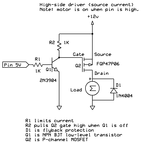
Here's the circuit:
When I supply the gate on the MOSFET with 5V via pin 46, I read 9 V on the drain. The drain reads 9V when pin 46 if HIGH OR LOW (ie switch is always on).
If I remove the 9V battery from the circuit, and add 5V instead to the source, I have no problem turning the flow on and off at the gate.
Can anyone suggest why my switch circuit only works with 5V and not a 9V battery? Should I be using a different MOSFET?
Are you sure you don't have the drain and source pins swapped? If you did, the MOSFET would always behave as if on due to the inherent body diode in the device.
I doubled check the pins. They don't appear switched. If they were switched then I wouldn't be able to turn off the switch using the 5V SRC.
It does look like I have to supply 9V at the gate using a NPN transistor:
"Things get more complicated if we need to source more than 5V, because to turn the MOSFET on we have to have a VGS of -5V or more (the Gate needs to be -5 relative to the Source, which is the opposite compared to an N-channel MOSFET). To turn it off we need to be able to set VGS to zero. So, for example, if we need to source 12V then to turn the MOSFET off we have to present 12V at the Gate. This can't be done with the Arduino output pin. To achieve this, we need a "helper" transistor, like this:"
Even if the output of the Arduino is high, i.e. at +5V, then it is still at -4V with respect to the +9V of the battery. That 4V difference may be enough to turn the P channel FET on continuously.
Yes, correct.
The resistor values are fine with me.
The 9V battery powers the fan. That means that current from the (+) side of the battery flows into the mosfet and through the fan can returns back into the battery.
However that current is going through the Arduino board, since you connected it to GND1.
I prefer to avoid ground currents going through the Arduino board. Can you redirect that so the current from the fan returns directly to the battery ? Don't forget to connect that also to the Arduino GND.
A good point to connect all GND (and also '-' side of batteries) is at the GND of the 5V voltage regulator.
When 5V is applied to VIN, the on-board diode drops the voltage to 4.4V, and that could be too low.
You pointed out a couple errors in my schematic that aren't reflected it my actual setup. I did notice that my Arduino was behaving kind of flakey (explained by the voltage drop by onboard diode) when supplying it the VIN with 5V from the down regulator.
To supply power to the Arduino, I am bypassing the down regulator and sourcing 7.4V directly from the battery to the VIN pin. I think eventually I might upgrade to a 11.1V Lipo.
All GND are now connected to an external circuit that is attached to the GND of the voltage regulator instead of going through Arduino board.
Here's my updated schematic:
I built the first segment of the circuit that has NPN transistor (PN2222A) and am able to switch the 9V from the battery supply on or off.
So my question is now, do I even need the P Channel MOSFET? All I wanted to do was control 9V power to the fans, and it seems that the MOSFET is now a redundant switch in the circuit.
I'm using this circuit to power two 9V fans that draw .5 Amps total.
The 2N2222 can do 300mA
The PN2222A can do 600mA or 1A (it depends on which datasheet is used).
That is too close to 500mA.
If you want a single transistor, you could try a darlington transistor like the TIP120. But darlington transistors are no fun, they have a large voltag drop.
Two transistors is possible. For exampe two BC337 transistors, each to a fan. The BC337 can do 800mA.
I would keep the mosfet, you might want to add a led or an extra fan some day. Or perhaps when you have forgotten the circuit and the fan starts making noise. If you replace it with a fan that requires more current, then it would be nice if the circuit can handle that.
P.S.: If you live in the US, you might prefer 2N2222 and alike. If you live in Europe, then BC547 and BC337 are normal transistors. We don't like the 2N2222 in Europe
Yes, for a mosfet it is normal that a 24A mosfet is used to switch two 0.25A devices. That means that the mosfet can switch 96 fans It is possible to use a smaller mosfet, but there is no need to. This is a normal situation (for a mosfet).
Sparkfun has selected the NDP6020P because it can be used for so many things.
I got the circuit soldered with the transistor and MOSFET and everything seems to be working. I can toggle the fans off and on. Really appreciate all the help getting.
TomGeorge - You bring up a good point about battery life. The reason why I migrated the fans away from the main LIPO was that they were drawing too much power and causing my LEDs to dim.
I am using a 9V smoke detector battery for the fans. If I use a single 9V Duracell for two fans that use .5 A it seems I'll only get around 1/2 hr of run time. Is that correct?
These fans are a cooling system for a helmet, and won't be ON all the time.
Should I get another LIPO (11.1V Lipo) with another step down regulator to 9V? Or maybe a battery holder that has 6 x AA's? That's a lot of extra hardware. Are there smaller profile options to provide 9V with a high mA?
I found Li-Ion batteries that look like they may do the job. I just need to figure out how to step down or step up the voltages:
About 30 minutes is what the battery can do, but it might just as well be 10 minutes. I would not be surprised if it was only 2 minutes.
If you buy an unknown brand Li-ion battery, half the battery might be cardboard or mud.
Are you stuck with the 9V fans ? Do they run at 5V ?
The Arduino can run at with 9V to VIN or to the power jack. I prefer a single Li-ion or Lipo cell for power (easier to charge), that means you would need a single 3.7 to 9V boost converter for both the fans and the Arduino.
Which Arduino board do you use ? That is not an Arduino Mega 2560 I hope ?