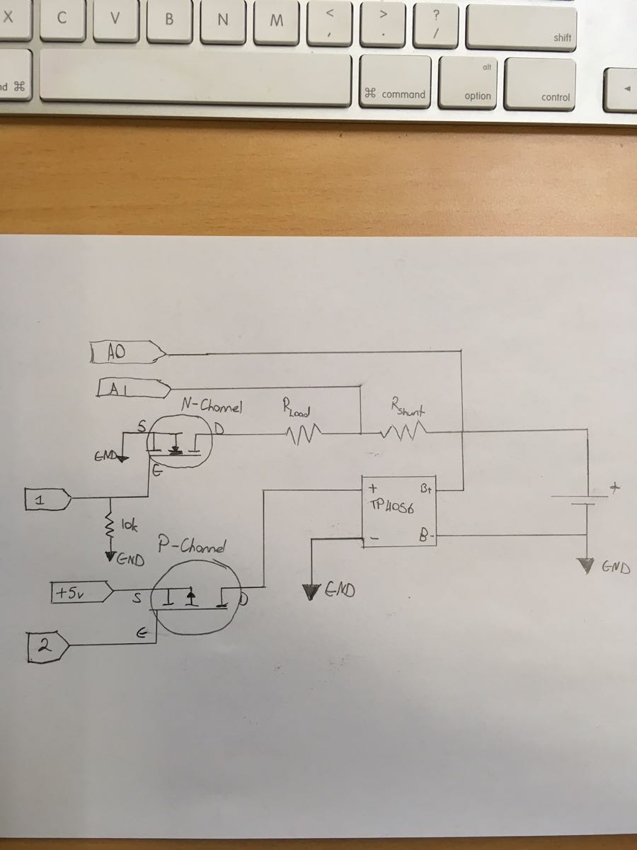
For my project I want to turn on and off a TP4056 18650 charger module. Unfortunately I can't use a N channel MOSFET as I believe the grounds are tied together.
Can I use this MOSFET without needing another transistor? Bearing in mind the Source voltage is also 5v.
Pin 1 and 2 are digital IO pins and A0 and A1 are analog.
The project is to make a tester which will charge the battery up. Once charged it will then discharge the battery until its flat, display the capacity in mAh then charge it back up again.
Will have a bit more of a play around tonight. The code works, it currently was only getting about 4.5 to 4.8v through which isn't enough to properly power the TP4056 module to charge correctly.
You also need to rearrange the Rshunt so its in the source of the FET. As currently drawn the A0 input (and likely A1) will be above the 5+ of the arduino. Will not work and likely toast the arduino.
In a Mosfet the gate current is essentially zero. So Rshunt in the source will keep it below the 5+ supply without introducing circuit current errors.
A suggestion when drawing schematics. Never make a +(cross) connection. If you moved the A0 line so it did not line up with the B+ line there would be no question if it was connected or just crossed lines.
The batteries I'm using at 18650 cells that are 4.2v max which is below the tolerances of the Analog Input.
The cross connection is meant to be there, as it needs to charge the battery but also read the voltage of the battery when the charger is off. Charger puts out a maximum of 4.2v as well.
The Rshunt is a very low resistance resistor, 0.5ohm and the Rload is a 3ohm resistor. Which would make the current draw 1.2 amps at most.
I hope this clears up why I've done it this way. If it's still incorrect I'm open to suggestions haha
I've decided to go down the route of detecting when the charge pin on the chip is pulled low to detect when the cell is charged. This would then turn the module off and start the discharge cycle.
The logic goes something like this.
Wait until a cell is inserted into the holder. If the cell voltage is above a minimum then turn on the module (P Channel MOSFET) and start charging.
Once the chips charged pin is pulled low turn off the charger and turn on the discharge circuit with the N Channel MOSFET. Display the mAh reading from calculations done with the shunt and load resistors.
Once the cell has hit its minimum voltage then turn off to the discharge part and turn the charger back on. Wait until charged and display on screen charged and the mAh for that cell.
Rinse and repeat for all cells to be tested.
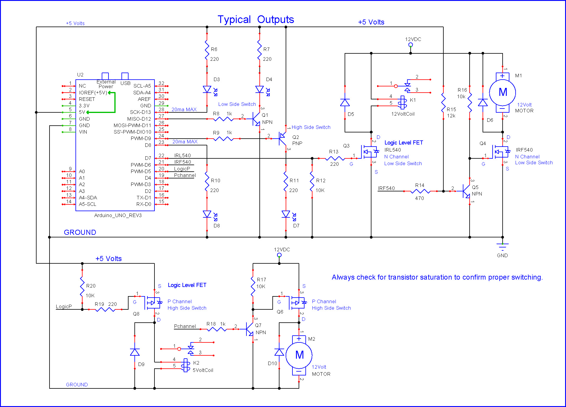
Thanks larryd for that schematic. It worked perfectly.
Thanks to everyone for your input.
I'm planning on using an ATmega1248 on a protoboard for the final part and will post up my schematics and sketch for anyone interested in doing the same thing.
Amazing helpful community here, thank you so much.
One thing that may not be obvious but worth being aware of is that that MOSFET has an absolute
max gate-source voltage of +/-8V, which means it is not intended for > 5V operation (its really
designed for modern logic, ie less than 5V), and you'd better ensure your 5V rail is clean without
voltage spikes to avoid the possibility of blowing the gate-oxide on the MOSFET. So I'd suggest
having a reasonable amount of decoupling capacitance on your 5V rail close to the MOSFET.