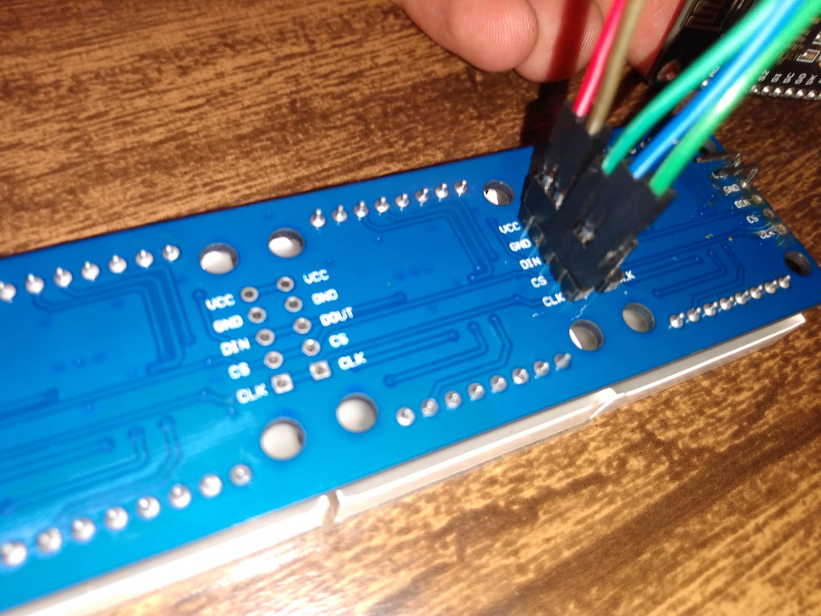
Hey i am using a Parola display with the base as 2 8x32 boards and on top 8 8x8 led displays, i had a problem with the first connections at the right of the modules and now i am using from the second contacts the VCC GND DIN CS CLK i want to now if this is gonna change something in the code, because mine is not working.
i am using this libraries at the moment #include <MD_Parola.h> #include <MD_MAX72xx.h> #include <SPI.h>
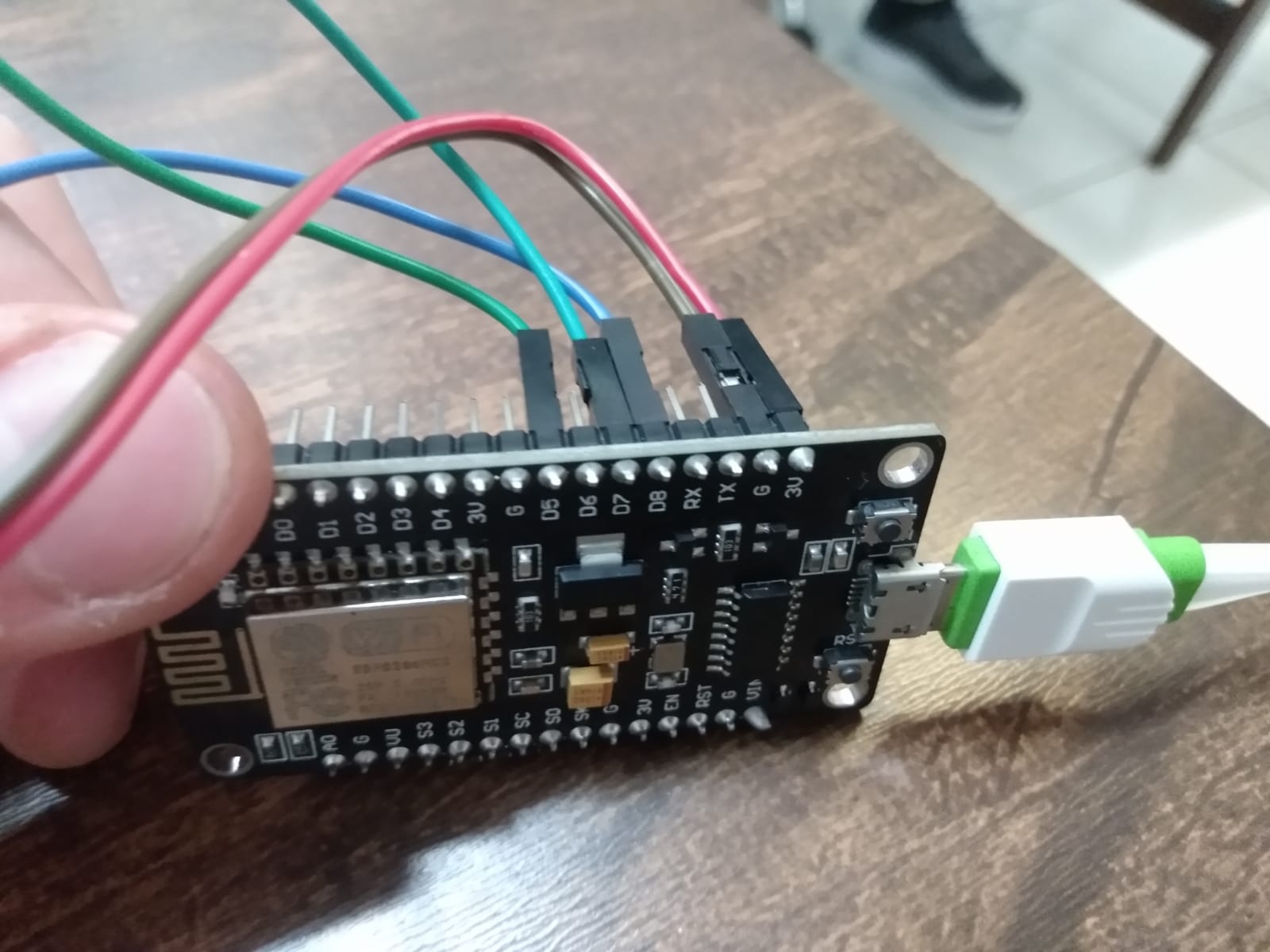
Your post is not clear. Can you please post code and/or a photo of what the connections are.
The code supplied as examples needs to be modified for the ESP32. If you are using the standard hardware SPI interface then you will need to ensure that the CS pin matches.; SPI2 needs a different constructor (read the library documentation) and 'any pin' SPI will need the correct pins specified in the application for the library to use.
You need to connect to the end. The MAX7219 chips pass the serial data (DAT) from one IC to the next, so this signal needs to be injected at the start of the chain of modules. All the others can be connected anywhere however it is usual to connect them all at the starting end.
The power supply to the modules must be directly connected to +5V and make sure the grounds (ESP and modules) are all connected together in at least one place. The digital signals from the ESP must be converted to 5V. The 3V signal may work for a few modules, but once you get past 4 modules it usually does not work well as the voltage for CLK and CS degrades enough to fall below the '0' logic level.