Passive Radar platform using Stepper and Rotary encoder

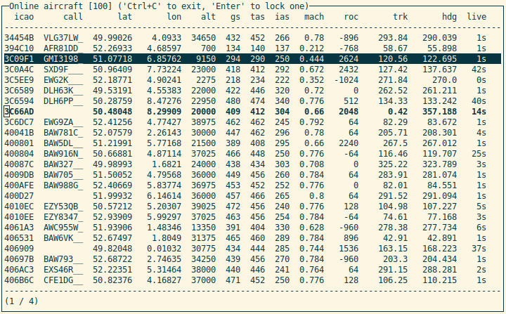
Hello, I'm currently working on my thesis, where I'm utilizing a custom-built Yagi Antenna to capture ADS-B messages, which I then decode using tools like pyModeS and RTL-SDR, among others. One of the challenges I'm facing is integrating my Python script with stepper motor control, possibly through UART communication.

My objective initially is to generate a simulated signal in Python to instruct the stepper motor to rotate either clockwise or counterclockwise. This is to prevent cable entanglement with my antenna setup on the platform.

Eventually, I aim to replace this simulated signal with a command like "track this ADS-B data package: XYZ, rotate CW/CCW until reaching the 180-degree limit" to optimize signal reception by following aircraft movements.
Another command I'm considering is to "Scan the airspace by rotating clockwise until the encoder indicates it's reached its limit. After that, rotate counterclockwise until the encoder signals the limit."

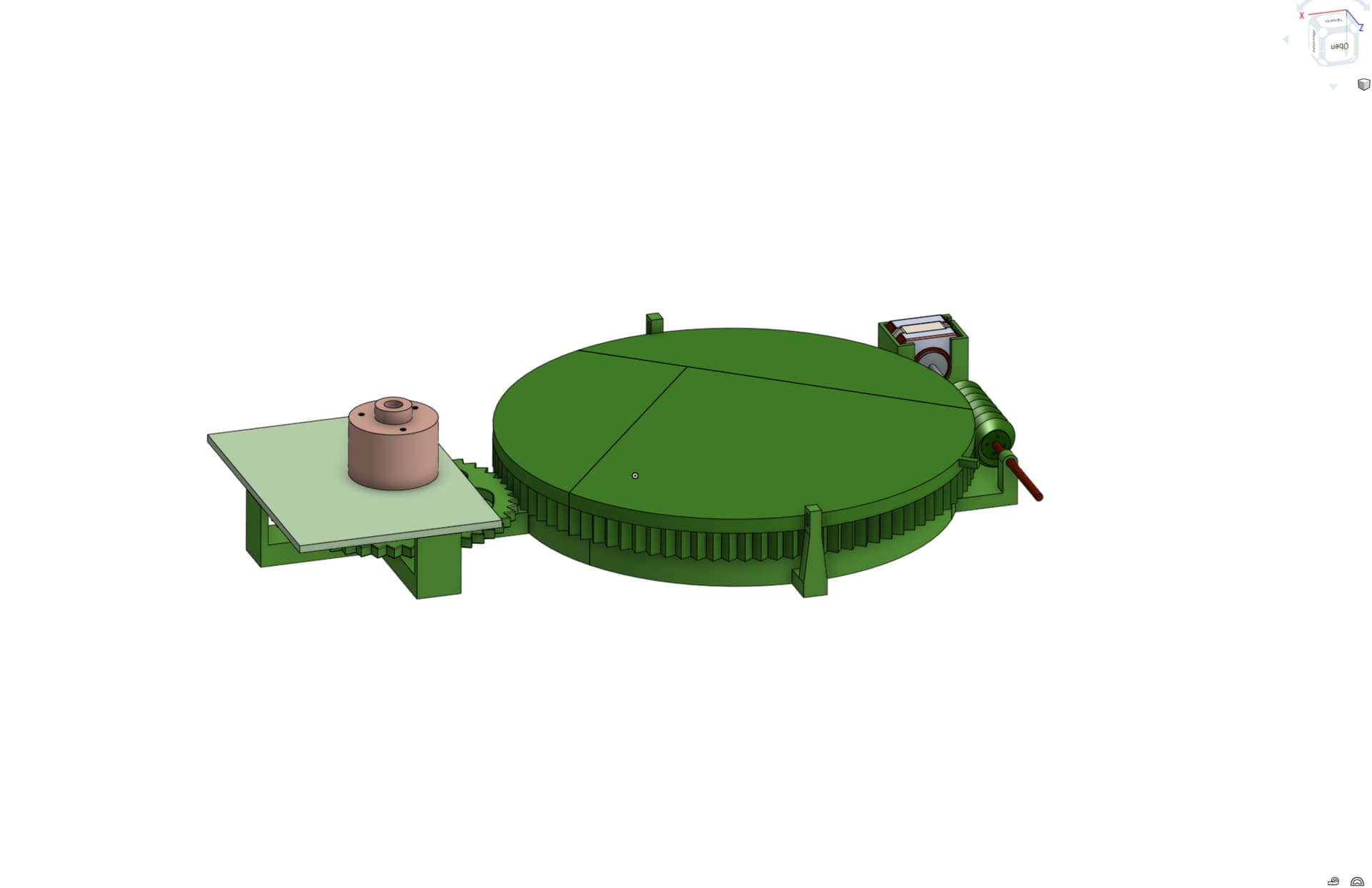
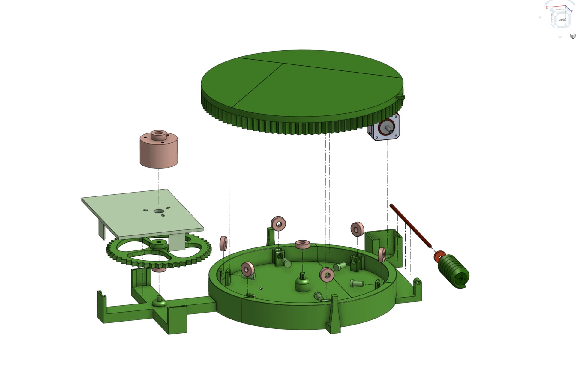
I have a rotating platform equipped with a stepper motor connected to a worm gear mechanism. To restrict rotation, I plan to incorporate an incremental rotary encoder from Baumer Electric. Datasheet of rotary encoder: https://www.baumer.com/medias/__secure__/Baumer_BRIH40_EcoMag_DS_EN.pdf?mediaPK=8800786513950

In the code below, I've started by using the rotary encoder as a control input for the stepper motor to familiarize myself with the hardware.

#include <Stepper.h>

// Define number of steps per revolution:
const int stepsPerRevolution = 200;

#define pwmA 3
#define pwmB 11
#define brakeA 9
#define brakeB 8
#define dirA 12
#define dirB 13

// Initialize the stepper library on the motor shield:
Stepper myStepper = Stepper(stepsPerRevolution, dirA, dirB);

volatile boolean TurnDetected;       // volatile needed for Interrupts
volatile boolean rotationdirection;  // CW or CCW rotation

// Rotary Encoder Module connections
const int PinCLK = 2;  // Generating interrupts using CLK signal
const int PinDT = 3;   // Reading DT signal

int StepsToTake = 1;  // Controls the speed of the Stepper per Rotary click

// Interrupt routine runs if CLK goes from HIGH to LOW
void rotarydetect() {
  // Read the state of the DT pin
  rotationdirection = digitalRead(PinDT);

  // Set the flag to indicate rotation detected
  TurnDetected = true;
}

void setup() {
  // Set the PWM and brake pins so that the direction pins can be used to control the motor:
  pinMode(pwmA, OUTPUT);
  pinMode(pwmB, OUTPUT);
  pinMode(brakeA, OUTPUT);
  pinMode(brakeB, OUTPUT);

  digitalWrite(pwmA, HIGH);
  digitalWrite(pwmB, HIGH);
  digitalWrite(brakeA, LOW);
  digitalWrite(brakeB, LOW);

  // Set the motor speed (RPMs):
  myStepper.setSpeed(30);

  pinMode(PinCLK, INPUT);  // Set Pin to Input
  pinMode(PinDT, INPUT);

  // Enable pull-up resistor for CLK pin
  digitalWrite(PinCLK, HIGH);

  // Attach interrupt to the CLK pin
  attachInterrupt(digitalPinToInterrupt(PinCLK), rotarydetect, FALLING);
}

void loop() {
  if (TurnDetected) {
    TurnDetected = false;  // Reset flag

    // Move the stepper motor based on the calculated StepsToTake and rotation direction
    if (rotationdirection) {
      myStepper.step(StepsToTake);
    } else {
      myStepper.step(-StepsToTake);
    }
  }
}

Do you have any suggestions on how I could approach this task? I'd greatly appreciate any input you can provide. Thank you in advance for your response.

in an application for a radar simulator I found it simpler to use hall effect switches and magnets to set the limits of rotation
what microcontroller are you using?

As a backup plan, I've considered implementing a limit switch where the platform mechanically triggers at either extreme using a "hook" mechanism.

Hall sensors hadn't crossed my mind until now.

I'm currently utilizing an Arduino Uno, powered with the Arduino MotorShield for motor control.

hall effect switches are more reliable than mechanical limit switches and don't bounce. Magnets were attached to the rotating antenna which used an ultrasonic sensor to detect persons in the area.
a Raspberry Pi displayed a simulation of a radar display using echos from the ultrasonic sensor
image

All of my rotating amateur radio antennas also have PHYSICAL stops, just in case I don't stop the rotation soon enough. I suggest you also have such safety devices.

Indeed, I've come across setups employing "radar" with similar sensors, but for my application, I prefer to utilize an encoder. With an encoder, I can obtain precise positional feedback, enabling me to determine specific angles, such as the antenna pointing at 57 degrees North East, and so forth. This level of positional accuracy isn't achievable with a hall effect switch.

I'm envisioning a user interface akin to pyModeS, where I can designate an ICAO code and direct the antenna towards its position. This interface would operate based on rules such as "if the signal strength of designated Package XYZ falls below -5dB, rotate 10 degrees clockwise; if the signal strength doesn't improve, rotate 20 degrees counterclockwise," and so forth.

Example on the UI:

In my 3D-printed base, where the platform rotates, I've also incorporated cutouts for two limit switches. If I have additional time, I'm considering implementing these switches as an added safety feature.

Hardware:

Explosion Photo: if it enhances comprehension:

You REALLY need HARD stops.
Looking at your code, I thought I would see some where in setup where you calibrate you machine to zero before continuing to loop(), but nothing there. So how do you know how to set the zero, beginning, for your rotary encoder?

Addition. I live in a rather windy location and sometimes have problems with Yagi antennas and rotators and wind. The wind loves to twist antenna mountings.

how do you zero the rotary encoder?
in the simulation I use move clockwise until the hall effect switch gives the zero position and then the movements of the stepper motor gives position
however, it is only a simple simulation and no attempt to get an accurate direction

My concept involves saving the position into a Direct Memory Access (DMA) so that each time the Python script issues a command, the Arduino retrieves the last position it was in.

However, my sketch hasn't reached that stage yet. I've only utilized it to control the stepper motor, familiarizing myself with this specific decoder.

The real challenge lies in integrating positional data into the control of my stepper. My stepper needs to be aware of the platform's position. The platform and encoder gear ratio is 2:1. Additionally, I need to implement limits on the encoder, allowing rotation until XYZ degrees are reached, at which point it should stop the stepper from rotating further.

Its my first Post, i dont know is there a limit on replying?

Maybe in the thousands. Usually the limit is when a problem is solved or people give up. You seem a long way from either!

Good to know, thank you.

do you mean a ROM or FRAM ? be careful ROMs have a limited write life - how often do you intend to save to it? if in any doubt use an FRAM

I've been considering implementing a memory feature where I can manually rotate the platform to its full right and full left positions, and then record these positions into memory. The Arduino would retrieve this memory every time it's accessed by Python. The "home" position wouldn't be determined by reaching a limit, but rather by the last recorded position retrieved from memory. This way, the sensor would have the information on how many degrees are left until a full right or full left rotation.

Given that the Arduino only retrieves the memory when called upon by the Python script and saves its last position for the subsequent Python call, it shouldn't be accessed frequently. As for the other recorded positions from two call-ups and further back, they can be overwritten.

my main problem was the radar simulation was in a museum and was switched off when it closed. The antenna could be anywhere in its sweep. On power up it rotated clockwise until the hall effect switch indicated zero position then operated as normal using the stepper motor to determine position.
what happens if your system looses power?

This is a aspect that I'm still in the process of understanding. From my research, I've learned that it's feasible to store data on EEPROM and utilize it as memory that can be erased and replaced with new data.

For controlling the stepper motor's movement or stopping it via Python, I'm considering utilizing UART communication. However, I haven't found a definitive solution yet.

As a step towards understanding this better, I plan to simulate Python commands with a basic code that controls the stepper motor in both forward and backward directions using the encoder for positional guidance and limiting. In this setup, the Python script would only issue commands for clockwise (CW) and counterclockwise (CCW) movements. The Arduino sketch would involve establishing a serial connection and integrating the encoder for limiting and positional guidance.

To proceed with the simulation, I'm seeking guidance in this forum on how to incorporate the rotary encoder as a sensor for limiting and positional guidance using my sketch to controll the stepper CW or CCW.

how often will you write position data to the EEPROM ?
e.g. every step of the stepper motor?
how often would you step the motor ?
what happens if you issue the command to step the motor and the power fails before you update the EEPROM?

Perhaps, saving the position in memory every 200 steps or once a limit of +90 degrees or -90 degrees is reached could be a suitable plan. However, it's worth considering whether saving the position every step of the stepper would be more appropriate.

Regarding the possibility of a power failure before updating, if the position is saved every step of the stepper, there wouldn't be catastrophic consequences. However, with less frequent updates, such as every 200 steps or at the limits, there might be a risk of losing some positional data in the event of a power failure. It ultimately depends on the level of precision and robustness required, However, I'm not prioritizing that aspect at the moment. My current focus is on making the decoder function as a limit first without faving the position in a memory. Once that hurdle is overcome, I can delve into solving the other questions. Once I've successfully implemented the limiter as required, the next step would involve saving the position and retrieving it from memory upon startup.

Alright, I attempted a different approach with a custom code to utilize the encoder for readout and control of the stepper. However, I encountered a persistent issue: when attempting to read out the encoder independently, I received unintelligible serial output.

The stepper successfully completes its 8000 steps, but without utilizing an interrupt and disregarding the encoder, it continues rotating until all 8000 steps are completed. Subsequently, upon completing the steps, the serial output starts displaying nonsensical characters. Despite searching various forums, I haven't found a solution or guidance on resolving this issue.

Could the problem lie in my encoder connection? Furthermore, how can I enhance the encoder's functionality to ensure the stepper halts precisely at the midpoint of its 8000-step rotation when it reaches its maximum or minimum value?

#include <Stepper.h>
#include <Encoder.h>

#define ENC_A 2
#define ENC_B 3

#define min_encoder_value -1000
#define max_encoder_value 1000

Encoder encoder(ENC_A, ENC_B);

// Define number of steps per revolution:
const int stepsPerRevolution = 200;

#define pwmA 3
#define pwmB 11
#define brakeA 9
#define brakeB 8
#define dirA 12
#define dirB 13

// Initialize the stepper library on the motor shield:
Stepper myStepper = Stepper(stepsPerRevolution, dirA, dirB);

void setup() {
  // Set the PWM and brake pins so that the direction pins can be used to control the motor:
  pinMode(pwmA, OUTPUT);
  pinMode(pwmB, OUTPUT);
  pinMode(brakeA, OUTPUT);
  pinMode(brakeB, OUTPUT);

  digitalWrite(pwmA, HIGH);
  digitalWrite(pwmB, HIGH);
  digitalWrite(brakeA, LOW);
  digitalWrite(brakeB, LOW);

  // Set the motor speed (RPMs):
  myStepper.setSpeed(30);

  Serial.begin(9600);
}

void loop() {
  long encoderValue = encoder.read();

  Serial.println(encoderValue);

  if (encoderValue >= max_encoder_value) {
    myStepper.step(-8000);
  } else if (encoderValue >= min_encoder_value) {
    myStepper.step(8000);
  }
}

I appreciate any assistance in advance.