the voltage drop across 10 meter seems to be marginal

Wires also have inductance, especially long ones.
is there a way to calculate it? or I just should do trial with long wire and see if or how it affect the motors?
Yes but how will that help you?
Here is a calculator that gives a theoretical value
https://www.allaboutcircuits.com/tools/wire-self-inductance-calculator/
It's part of the allaboutcircuits online text book that I suggested you read.
or I just should do trial
Good idea.
As far as capacitors, you should also have a .1uF cap across the PWM chip Vcc-GND
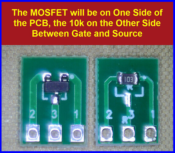
ok, I found this 4 channel mosfet driver board: link (the green one)
it can operate with 3.7V output which is close enough to my 3.3V motors (?) so it might be a good solution?
FFS it's only 70mA and a PCA9685 can only do about 1kHz PWM.
I suggested an ULN for simplicity. You don't need any other parts than the ULN itself.
And you can use a 5volt supply.
Just use one ULN fer 8 motors. Join ULN inputs as required.
Build it, test it, get on with life.
Leo..
2 Likes
Your guess would be as good as mine. I have doubts about many of the claimed specifications.
It does not seem like you want to try to learn anything.
I just ordered the PCA9858 and I will try the circuits offered and see what is works.
In worst case scenario I will get Arduino Mega and Will control each of the motors from individual PWM pin (15 in total).
Yesterday I build the circuit with FQP30N06L that I had at home and it did not work at all (I guess due to fake part that was bought from Aliexpress).
I then check using 2N2222A transistor with 330R base resistor and it was working great. I might use that instead of the MOSFET.
The idea to use the MOSFET was that I could potentially drive different motors that require higher current. But I might just use 2N2222A to drive only those small motors.

Nothing wrong with that.
Buy extra parts and modules in case you burn out or damage something
1 Like
Some updates. board arrived. works great. I’m using MOSFET for driving the motors. for the moment tried with 4 motors. All works.
Thanks for all the helps
schematics:

Did you buy new MOSFETS because you said they did not work before.
See post #4

-
A few small things.
- As mentioned, the PCA might have 220R series output resistors. If so R1 is not needed.
- Your D2 Symbol is wrong.
-
I prefer connecting OE to GND even though there are 10k pull-downs.
-
High current output power supplies should have fusing.
-
How is the NANO powered ?
-
Avoid making a voltage divider, use this circuit.

Correct.
R2 is also not needed.
The gate is connected to a permanent output pin, not to an MCU pin that is an input during bootup.
Leo..
1 Like
- But my motors run by themselves when I unplug them from the PCA9685

![]()
Got you.
But hot-plugging a gate, with or without resistor, is not a wise thing to do.
The base of a 2N2222 transistor is more forgiving there.
Leo..

I did point that out back in post #4
Yes I did, those ones works
Thanks I will do that.
How is the NANO powered ?
For the testing I'm using Uno, it powered from the USB via the computer (that also control the motors via the Serial) . In the finished version I will use Nano that will be powered from the computer as well (via USB)
regarding the pulldown base resistor - is it needed? @Wawa thinks is not needed. Just reminder I’m using MOSFET and not the bjt
edit: updated schematics:
