Hi,
as title says, I'm looking for reliable power source for Esp32Cam.
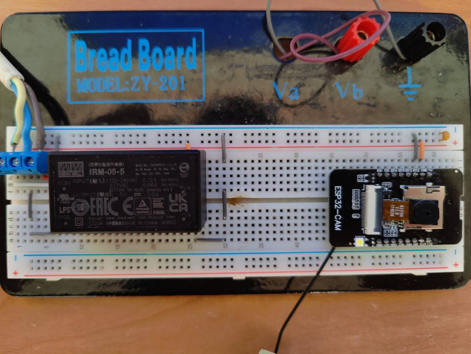
I was using this one for powering MKR1000, but no luck with Esp32Cam.
I have tried to add 104pF ceramic capacitor on the power rails, but didn't help.
Is there some obvious reason why this power source shouldn't work that I don't see? Is there something more I can try to "smooth" the output of this one to make ESP32 like it?
Can you elaborate on "no luck". You've linked to a 5V/2A medical grade supply that really doesn't need output filtering. I run an ESP32-CAM with the USB adapter board and power the lot with a 1A USB supply with no issues.
5V 10W, that's correct. it just wont start. the ESP32. I can measure 5V on the output. I have tried two ESPs: one with built in serial to usb and one without. One of them started for one time, I issued command via mqtt to take the photo at that moment it stopped working and didn't blinked since. Maybe I have a bad piece or something, ESPs are working on usb fine..
For a 3.3v device a 3.3v PSU seems more appropriate unless there are also 5v components to be powered. 2A seems like overkill though. But as stated before it should just work.
however, the power supply is not an issue; I added blinking to the setup() and I can see it [blink] and it repeats over and over. it's the WiFiManager that causes this loop. here's the code:
#include <WiFiManager.h>  // https://github.com/tzapu/WiFiManager

bool startIncuWifi() {
  WiFiManager wm;


  bool res = wm.autoConnect("AutoConnectAP", "password");  // password protected ap

  if (!res) {
    Serial.println("Failed to connect wifi");
  } else {
    Serial.println("wifi connected...yeey :)");
  }

  return res;
}

void setup() {
  Serial.begin(9600);

  pinMode(4, OUTPUT);

  digitalWrite(4, HIGH);  // turn the LED on (HIGH is the voltage level)
  delay(1000);                      // wait for a second
  digitalWrite(4, LOW);   // turn the LED off by making the voltage LOW
  delay(1000);

  digitalWrite(4, HIGH);  // turn the LED on (HIGH is the voltage level)
  delay(1000);                      // wait for a second
  digitalWrite(4, LOW);   // turn the LED off by making the voltage LOW
  delay(1000);

  startIncuWifi();
}

void loop() {
  // put your main code here, to run repeatedly:

}
well, my original sketch is way more complex, I initialize mqtt, air sensor, wifi, camera and temp sensor and pass around some delegates in order to keep code separated in files... it's just what was left after I was cutting the pices off in order to isolate the issue
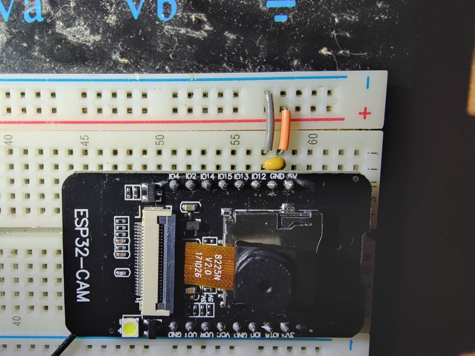
alright, solved now and it was power issue at the end.
what worked is putting the little ceramic capacitor closer to the ESP32 pins. before, I had it on the end of power rails, also it needs to have that 2A power source, on the 1A which I photographed it still wont work, but with 10W 5V it is enough.
WiFi communication involves peak currents in the range of a few hundred mA. Apparently your power supply destabilized under these conditions, forcing the ESP in a brownout condition or a reset loop. Generally a 5W power supply is more than adequate with decent circuit design, unless there are other power-hungry components part of the system.