Now you are designing like a real engineer.
Makes no sense.
However, the LM2596 is not well suited for regulating small loads. Personally I would look for a regulator that has max range of maybe 0.75A to 1A
From the datasheet
8.4.1 Discontinuous Mode Operation
The selection guide chooses inductor values suitable for continuous mode operation, but for low current applications or high input voltages, a discontinuous mode design can be a better choice. A discontinuous mode design can use an inductor that can be physically smaller, and can require only one half to one third the inductance value required for a continuous mode design.
I think 15uH would be the right choice. Unless we choose a different regulator.
Stay away from discontinuous mode. It will have higher output ripple and poorer voltage regulation. If you don't get the design just right and it switches between continuous and discontinuous mode you will have serious voltage transients.
Have a look at the LM2575.
1 Like
Thanks for the guidance. Will go through the datasheet properly this time, will share the revised schematic by tomorrow.
I can't thank you enough. I wouldn't have been able to do it on my own.
Use this datasheet. TI screwed up the F rev
LM2575HVS-ADJ-NOPB.pdf (5.9 MB)
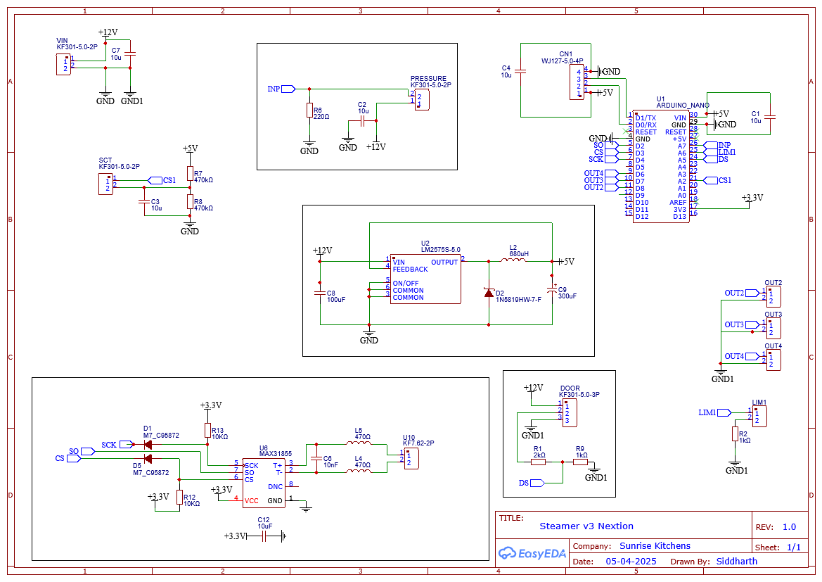
Vin on the nano need to be 7>=Vin =<12
Still have not followed manufacturer recommendations for the MAX31855.
Still have my doubts about the limit switch and prox sensor circuit. May seem like they are working but according to datasheet they should not.
Regarding MAX31855, I went through the datasheet multiple times. It doesn't discuss the schematic much. Except for the need to add capacitors across VCC and GND, and T+ and T-; which I have already incorporated.
Schematic from Adafruit website, also appears to be in line.
Let me close this point first, before proceeding with the limit switch and proximity sensor.
From the datasheet:
"The effects of power-supply noise can be
minimized by placing a 0.1µF ceramic bypass capacitor
close to the VCC pin of the device and to GND."
You can keep the 10uF but the 0.1uF is a must.
As you can see Adafruit also did it wrong. Don't assume anything published by Adafruit is correct.
1 Like
Proximity Sensor
Found my mistake again. And it took me some time to understand what I did wrong. I also did a small prototype to validate the new design.

Something wrong!
You previously said that you measured 4V at DS without the 4.7K in the circuit. See post #11 and #12.
That is correct, I did that prototype. But I must have done something wrong the previous time. I did the same test today.
As per the previous layout, the output black wire provides a 12V output when the circuit is not complete. When three 1kΩ resistors are connected in series to the black wire, and to the V-pin, the output voltage at the black wire drops to 4.5V.
Well that makes sense. So why have you decided to add the 4.7K resistor?
Yes sir. That is correct.
And you had raised concern how I use the limit switch. I am working on that too, will post again soon.
You better get that circuit correct, don't want to destroy the Arduino. That sensor is an NPN normally closed output. It may or may not have an internal pull-up resistor to 12V. You need to first find out if it does. Measure the voltage at the black wire when it detects something and when it does not detect something. If you see 12V when something is detected then there is an internal pull-up.
If there is no internal pull-up then it is safer to use a 10K pullup to 5V rather than to 12V and no need for the voltage divider.
Hi,
The proximity sensor has a built-in internal pull-up resistor of 10k.
I am again going back on my words. When I had completed the circuit last time with some resistors, the black wire output voltage was 4.5V. Now it's around 11.5V.
I am just lost. What mistake did I make the last time!
But in either of the case, an additional 4.7kohm pull up resistor to +12V will do no harm, and not use pull up to 5V.
The mistake you made this time is that you did not do what I asked in post #36
It gives a voltage of 11.5V when an object is detected. Supply voltage from SMPS is close to 13V.
When no object is detected, the voltage in black wire is 0.
