DrDaveyG:
Oh really. It is that much of a hassle to get them lined up?
I assume alignment is the disastrous part?
If you use through-hole connectors, then you have a whole lot of holes in the circuit boards to be in perfect alignment. Can your board mgf do that? IF using SMT connectors, how will you place them and solder them so they will align. Will the SMT connectors withstand being pulled apart several time?
DrDaveyG:
Oh really. It is that much of a hassle to get them lined up?
I assume alignment is the disastrous part?
Not at all. You just need to solder the connectors with the boards already stacked so they point
in exactly the right directions as the solder solidifies. Decent connectors like Dupont are self-
centering.
Normally robust PCB mounting involves threaded stand-off pillars, which are available in metal
or nylon, so the mechanical connection is solid (and vibration can't wriggle them apart)
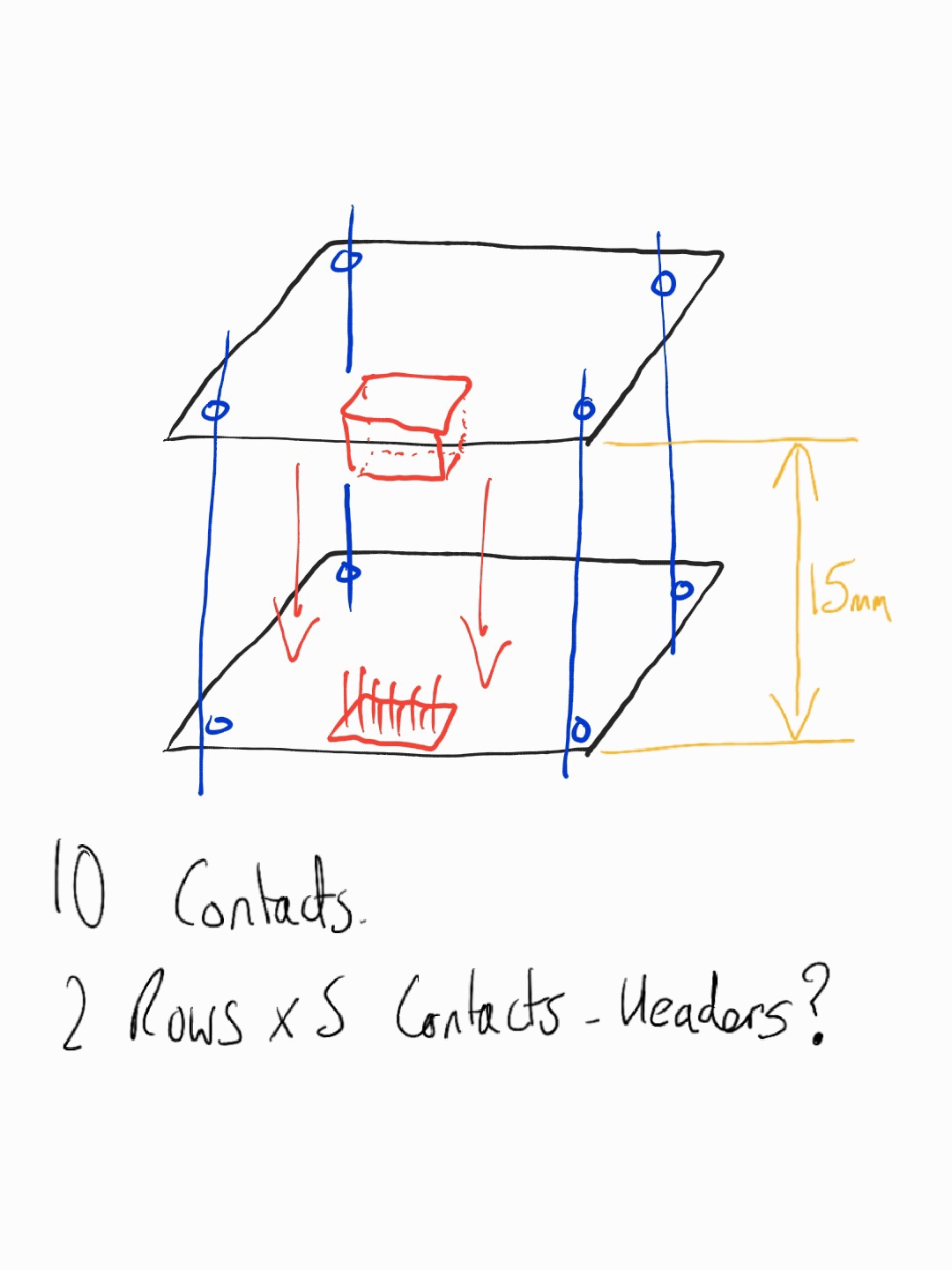
If you are going to use headers and pins then I would put at lease one at each corner of the boards for stability even if they are dummy ones that don't actually provide any connectivity
I ve also used headers just like in #8 with no problems at all. If the PCBs are large and the connecting headers relatively small I also use metal pillars with screw/nuts.
My PCBs are designed for SMD with the exception of headers which I use throughhole ones for added stability.
I have used 50 way connectors before and stacked 3 or 4 boards on top of each other. Also if you at the PC104 standard they can stack many boards.
If your PCB manufacturer can't manufacture your holes to align as per your PCB design then stop using backyarders. It is not that hard. it is up to you to get the holes in the right spot then it is all very easy. Don't be put off. Be adventurous.
I’ve done this, sandwiching two boards together with a matching 8 x 1 male/female 2.54mm through the hole header pair. Do a practice assembly of the boards prior to soldering the headers to get the alignment correct as already mentioned. From memory, the ideal length of the pillars to separate the boards is then 11mm (at least with the header pair I used). I could find only 12 mm pillars, so pushed the male pins a little deeper before soldering.