Hi guys,
recently I am working on a research project.
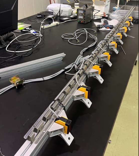
In my research, I need to build a machine that can record whether a person steps into the correct square. The prototype will look something like this.
So what I am trying to build is whenever some step into the wrong block,
the sensor will detect their foot, switch to NO and sending input to arduino.
I start with one sensor and connect the wires,
the brown wire connect to positive of power supply, and the blue and yellow wire connect to negative. I open the power supply and set the volt to 12.
The voltage difference between the brown wire and the black wire is 12 volts, measured with a multimeter. Seems to work just fine.
However, I’m having issues connect it to arduino.
Reduce DC voltage with resistor
The input voltage for Arduino should preferably not exceed 5 volts.
So I connect black wire--10 ohm --small piece of red wire -- 14 ohm -- GND of the power supply.
Measure the voltage between brown and small piece of red wire, still 12V.
The goal is to reduce the input to 5V so that I can work on the code on arduino.
How do I resolve this problem? Should I connect the GND between arduino and power supply? Or am I just do it wrong?
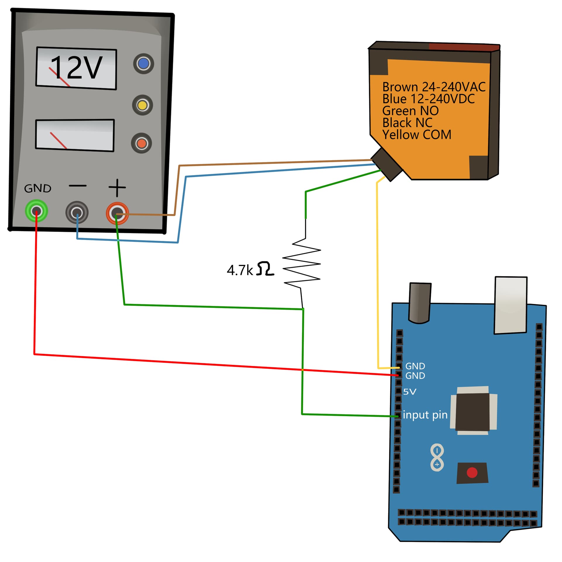
If the output will work with 5VDC then just connect the COM (yellow) to Arduino GND.
Connect a 4.7K resistor between the NO and 5V and also connect the NO to an Arduino pin.
Make sure that the 5V power supply ground is also connected to the Arduino GND
Thank you very much for the reply, will try it soon and share the result. PH&PR_Sensor_datasheet.pdf (1.4 MB)
The exact datasheet on page 14, it's mainly in english.
Low enough to help reduce noise pick-up but high enough so as not to draw too much current. It's a compromise. You may find you actually need a lower value.
I'm trying to understand it today, this is what I came up with so far:
1.Connecting yellow to GND of arduino is to let arduino had a refernce point to determine the signal voltage.
2.When the sensor detects an object, the yellow wire and black wire close to form a circuit, allowing 5V to flow into the input and eventually into the GND.
Actually the other way around.
When it is NOT triggered the yel and blk are disconnected so the 4.7K resistor applies 5V to the input pin and it will read HIGH
When triggered, the yel and blk are connected and the input pin is now connected to GND, so the input will read LOW.
It is a common circuit for detecting switch closures. The 4.7K resistor is called a pull-up resistor.
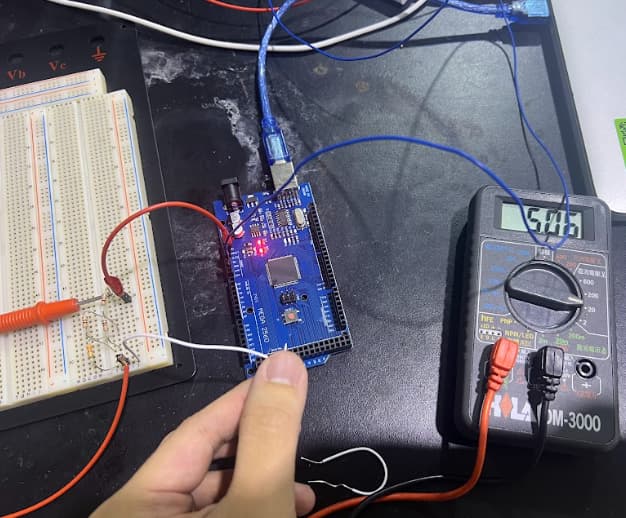
The way sensors connected to arduino and external power source is by the solution of jim-p, and I just parallel connect them. I also use a relay to light up the 12V LED.
The rule of the machine is it will semi-ramdom select a set to light up the LED, the subject needs to step in the cube. Here is the code : Arduino_project.txt (6.6 KB)
Hope it helps! For anyone might need it!
[1] Zhang, Z., Xiang, T., Guo, H., Ma, L., Guan, Z., & Fang, Y. (2023). Impact of physical and mental fatigue on construction workers’ unsafe behavior based on physiological measurement. Journal of safety research , 85 , 457-468.