Hello everybody, I've built a keyboard with my arduino uno and the breadbord simply with 4 buttons in parallel and 4 resistences, as the project's book says (pages 79-85).
Then, I'm trying to add some new frequencies (notes) pushing together 2 or more buttons, producing different values (in order to collocate a new frequence for each new value).
The problem is in the fact that I can only generate a new value pushing the last and the second-last button, while if I push other 2 (or more) buttons together the serial monitor says that the value produced is that of the first button I've just pushed.
The circuit is that in the attachment.
Is it normal that I can't have more new values? Why? Is there, instead, something wrong in the linkage, so I cannot create the new values?
int notes[]= {262, 294,330,349 }; // frequencies in Hz for do re mi fa fa


void setup() {
  // put your setup code here, to run once:
  Serial.begin(9600);

}

void loop() {
  // put your main code here, to run repeatedly:
  int keyVal = analogRead(A0);
  Serial.println(keyVal);
  if(keyVal >= 6 && keyVal<=9) { //pushing button 1
    tone(8,notes[0]);
  } else if(keyVal >= 510 && keyVal<=513) { //pushing button 2
    tone(8,notes[1]);
  }else if(keyVal >= 1000 && keyVal<= 1003) { //pushing button 3
    tone(8,notes[2]);
  } else if(keyVal == 1023) { //pushing button 4
    tone(8,notes[3]);
  }
  else { //pushing nothing
    noTone(8);
  }

}
As I said before, I would add, for example, the note "sol" pushing for example button 3 and button 4 at the same time, but the value shown on the screen (thanks to the Serial.println) is the same of that of button 3, so it's impossible for me to associate a new value to the frequency of the note sol.
The schematic is in the attachment, if it's what you meant before.
As I said before, I would add, for example, the note "sol" pushing for example button 3 and button 4 at the same time, but the value shown on the screen (thanks to the Serial.println) is the same of that of button 3, so it's impossible for me to associate a new value to the frequency of the note sol.
Before we go any further, I think we need to know where you stand with regard to electronics. This is the General Electronics Topic forum. You are asking questions about a circuit which is a simple voltage divider. We need to know if you actually KNOW what a voltage divider is and if you are familiar with ohm' Law. For example , you ask a question about pushing buttons 3 and 4 together. Button 3 is 10k and button 4 is 1 Meg. How much effect do you think a 1 Meg ohm resistor is going to have in parallel with a 10 k ohm resistor ? Do you see my point ? Have you done the math for each button ? (the voltage divider math) Do you KNOW how to do the math for the voltage dividers ? Have you Googled voltage dividers ? Do you know how to do the ADC conversions ? Do you know ANYTHING about HOW this circuit works ?
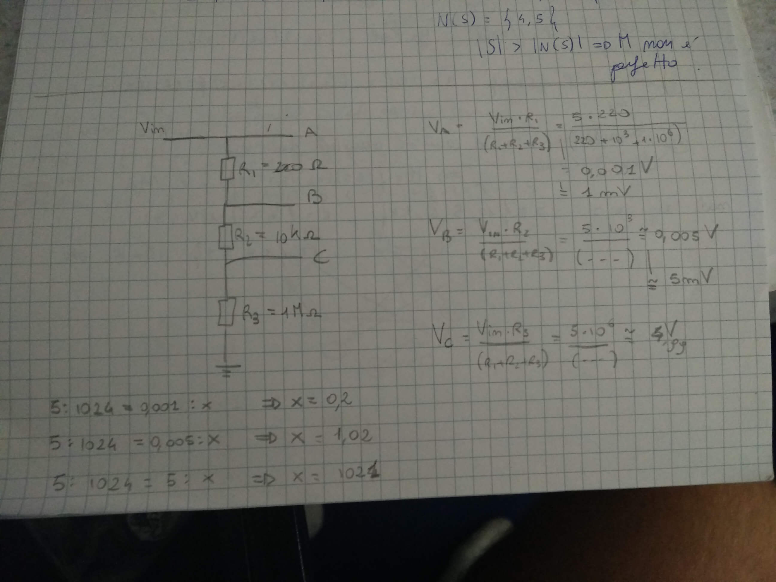
So, applying the rules for a voltage divider, we obtain that the voltage on the resistence A is given by the formula:
V(A) = VinA/(A+B+C) = 5220/(220+10^3 + 10^6) = 0.001V = 1mV.
Repeating this for B and C we obtain that:
V(B) = 0.005V = 5mV
and
V(C) = 4.99V
Converting voltage to values of arduino we obtain that:
n(V(A)): 5:1024=0.001:n => n= 0.2 => n=0 (because of the numbers converted are INT);
Button 1 = 5V....... .= 1023 analog counts
2 = 4.892 V = 1000 analog counts
3 = 2.5 V ... = 511 analog counts
(3+4) = 0.5025 V = 514 analog counts
4 = 0.049 V = 10 analog counts
Button 3+4 is 10k in parallel with 1 Meg which results in 10k/(9900 +10 k) = 10k/19900 = 0.5025 V
As you can see, the difference between Button 3 and Button 3+4 = 2.5125628 V - 2.5 V = 0.010 V
which may be 4 analog counts which may sound the same as button 3.
The difference between 10k and 10k || 1 Meg = (10000-9900) = 100 ohms
I tryed to attach the pic but it was too large, so I'm going to write the scheme.
Nowhere did you say you were changing the schematic design.
If you are now using the ladder network then my calcs don't apply because they were done for your OP.
Your calculation for button C in your posted calculations should be: 4.9495 V
The others are wrong too but I don't have time to do those right now because I have to leave for work. I will say that your mistake is the denominator should be everything BELOW the resistor in question :
VB should be (R2 + R3)/((R2 + R3) +R1) =(1 Meg +10 k)/ ( (1 Meg + 10 k) + 200) = 0.9998 => 5V * 0.9998 = 4.99 V
With what you posted last the voltage at A is always going to be the voltage at Vin. They are connected to the same point in the circuit so how could it be any different?
Remember the A/D in the Arduino is 10 bits, that means 1024 steps. With a 5V reference the steps are going to be 5/1024 V or 4.88mV.
The current down the chain is Vin / (1M + 10K + 200R ) = Vin/ 1010200 A or if Vin is 5V then the current is 4.96uA, lets call it 5uA.
So across the 200R resistor you will develop a voltage drop of 0.001V - about a fifth of a step from the A/D
Across the 10K you have 0.05V or about 10 steps.
With what you posted last the voltage at A is always going to be the voltage at Vin. They are connected to the same point in the circuit so how could it be any different?
Agreed. Vin = 5V so there is NO voltage divider
Remember the A/D in the Arduino is 10 bits, that means 1024 steps. With a 5V reference the steps are going to be 5/1024 V or 4.88mV.
The current down the chain is Vin / (1M + 10K + 200R ) = Vin/ 1010200 A or if Vin is 5V then the current is 4.96uA, lets call it 5uA.
So across the 200R resistor you will develop a voltage drop of 0.001V - about a fifth of a step from the A/D
Across the 10K you have 0.05V or about 10 steps.
I agree with the calculations but since the ADC only draws 160 nA when reading an analog input I doubt it is a problem.
Guys I'm confused, and maybe I'm confusing you too.
From the book, I read:
"[...] for this project we could use a number of buttons for every different tone, but now we are going to use a ladder resistor network."
Last year I studied "electronics and electrotechnology" at University, but the teacher has never mentioned this kind of network, so I was trying to understand it all by myself, but I think I'm having troubles whith this..
I would follow what my book says, so I would try to apply this ladder resistor network to my circuit; the values of the resistences and the position of the buttons is all showed in the book, so I'm applying to my circuit what I see in the book (image on the attachment).
I know I should learn more about the ladder resistence network, but I was trying to do this applying it to my project (sometimes I think it's better learning by practice than learning by reading a book).
So, please, don't be angry with me if my book is giving me wrong resistence values or something else..
So, please, don't be angry with me if my book is giving me wrong resistence values
The book gives the right values. What you have is the wrong circuit.
The schematic -----753.jpg will not allow you to differentiate individual buttons. The other one will, but it is not how you wired things up in your reply #8. The resistors shown in that book however are not very well designed. They should be a power of two difference. So 200R 400R and 800R or 1K 2K 4K, or 20K 40K 80K, however 200R 10K and 1M are not very good.
So you're trying to push a whole bunch of buttons and get multiple frequencies right? That's 'polyphony'.
Maybe you can just have the arduino detecting the state of each key using a separate digital input (with debouncing circuitry to avoid bounce issues, if necessary) for each key.
1 key per digital input.
But then, later on - you might need to think about 'after touch', which is really basically extra features - like 'velocity sensing' - like.... how fast you push down on the key determines how loud a sound is played. But that would involve keys having velocity sensors.
So you're trying to push a whole bunch of buttons and get multiple frequencies right? That's 'polyphony'.
I don't think he is. What that circuit is designed to do is to detect how many buttons are being held down at one time. He said
Then, I'm trying to add some new frequencies (notes) pushing together 2 or more buttons, producing different values (in order to collocate a new frequence for each new value).
As I read that there is only one tone being generated at any one time.
Grumpy_Mike:
I don't think he is. What that circuit is designed to do is to detect how many buttons are being held down at one time. He said As I read that there is only one tone being generated at any one time.
I think you're right GM. I mis-interpreted when I saw the "pushing together 2 or more buttons" and "new frequencies"..... and 'piano'.
Is it more like a 5 finger type writer .... those ones where the user learns all the key combinations through training.... to generate their desired character?.....in this case ...a single note...so a person with 5 fingers could play 1 of 32 different notes?