Hi everyone, currently i'm trying to test giving a pid controlled dc motor a setpoint in degrees to go to. below is the code i'm using, kindly note that I'm using H2010 as my encoder and the void pulse function is the function to check for encoder pulses. while using this code going to a positive angle like; 90 or 45 degrees is working but going to a negative degree like; -45 or -90 degrees it just bugs. the error is when i use a negative set point the motor goes the setpoint in the negative direction just like how it should be but right after it it rotates in the positive direction for infinity.
for example, the setpoint is now -45, it will go to the -45 and then it will keep rotating in the other direction forever. So, kindly if anyone notices this kind of problems please help.
#define IN2 6
#define IN1 9
#define T_Samp 5
#define pulse_cm 0.4444444444 //pulse per rev
#define Sat_Max 255
#define Sat_Min -255
#define buttonstatePin 12

#define Setpoint -45
#define Kp 50
#define Ki 120
#define Kd 0


const int buttonPin = 2;    // the number of the pushbutton pin
// Variables will change:
int ledState  = HIGH;
int buttonState;             // the current reading from the input pin
int lastButtonState = LOW;   // the previous reading from the input pin
int count=0;

float ctime=0;
float dtime=0;
float prev_time=0;
float cur_dist=0;
float error=0;
float pid=0;
float sum_err=0;
float prev_err=0;
float pulses=0;

void setup() {
  Serial.begin(9600);
  //pinMode(ENCA,INPUT);
  //pinMode(channel_B_Motor_1,INPUT);
  pinMode(IN1,OUTPUT);
  pinMode(IN2,OUTPUT);
//  pinMode(PWM,OUTPUT);
  pinMode(buttonPin, INPUT);
  pinMode(buttonstatePin,INPUT_PULLUP);
  //attachInterrupt(digitalPinToInterrupt(ENCA),Pulses,RISING);
  attachInterrupt(digitalPinToInterrupt(buttonPin),Pulses,RISING);
}

void loop(){


    ctime = millis();
  dtime = ctime-prev_time;


if(dtime>=T_Samp){

cur_dist=count/pulse_cm;

error=Setpoint-cur_dist;

sum_err=error+prev_err;

pid=(Kp*error)+(Ki*sum_err*T_Samp)+(Kd*error/T_Samp);

prev_err=error;

if(pid>=Sat_Max){
  pid=Sat_Max;
}

if(pid<=Sat_Min){
  pid=Sat_Min;
}
//Serial.print("pid value=");
//Serial.print(pid);
//Serial.print("             Error=");
//Serial.println(error);


if(pid>0){
  //digitalWrite(IN1,HIGH);
  digitalWrite(IN2,LOW);
   analogWrite(IN1,pid);
}
else{
  //digitalWrite(IN2,HIGH);
  digitalWrite(IN1,LOW);
  analogWrite(IN2,-pid);
}
prev_time=ctime;

}// if dtime


} // void main


void Pulses() {
 int reading = digitalRead(buttonPin);
    if (reading != buttonState) {
      buttonState = reading;

      if (buttonState == HIGH) {
        ledState = !ledState;
        if(Setpoint<0){
          count--;
        }
        else{
          count++;
        }
    Serial.println(count);

      }
    }

  }
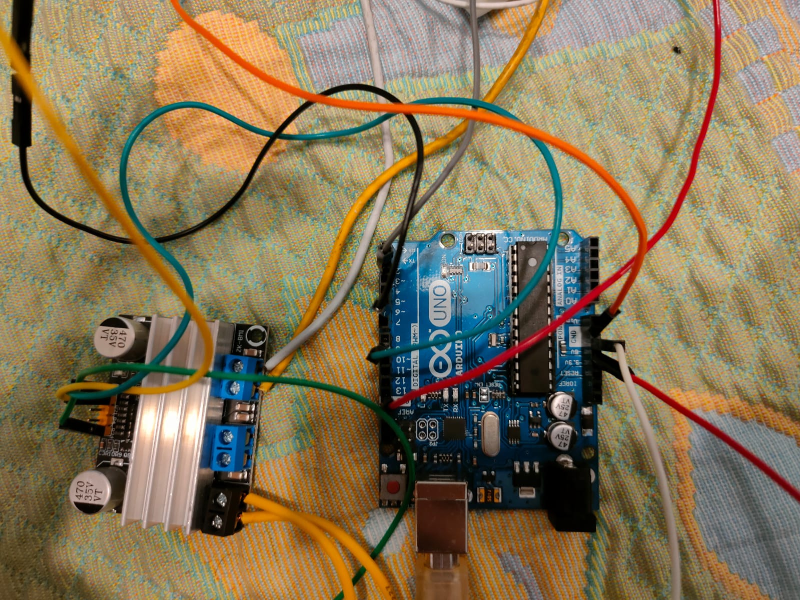
yes I'm sorry i forgot to mention, i'm using Zk-BM1 motor drive, it doesn't have pwm pins but it's IN pins supports pwm values, hence, i didn't use a pwm pin but instead i gave the pwm value to the used pins (maybe i'm not 100% right about it but it's working for the positive setpoints.
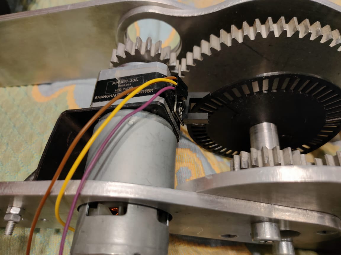
im using 755 dc motor along with H2010 encoder and ZK-BM1 motor driver
this is a picture of the wiring set for the arduino with the motor driver, i'm sorry it's nothing close to a formal picture.
the sequence should be that when i give a setpoint and start the code, the current distance and errors are calculated to be able to calculate the pid value cur_dist=count/pulse_cm; error=Setpoint-cur_dist; sum_err=error+prev_err; pid=(Kp*error)+(Ki*sum_err*T_Samp)+(Kd*error/T_Samp); prev_err=error;
in the same time the encoder keeps counting using the attachinterrupt function, and then the value of the count which is the number of the encoder pulses is used to calculate the current distance that is showed above.
then, according to the pid value the motor either moves clockwise or anti-clockwise.
the if condition using the dtime>=T_Samp is used to recalculate the values using millis() until the setpoint is reached.
-the motor IN pins are at 6 ,9
-the encoder pin is at 2
-the T_samp is used for millies delay, sat max and min is used for setting the pid value back to max and min of 255 and -255 if its value was beyond the max and min
-the buttonstatePin at 12 was removed and im sorry that i didn't remove it before uploading the post
-the code below is for checking that each rotation of the encoder desk only makes 1 pulse, because when its HIGH it might make more than 1 reading
const int buttonPin = 2;    // the number of the pushbutton pin
// Variables will change:
int ledState  = HIGH;
int buttonState;             // the current reading from the input pin
int lastButtonState = LOW;   // the previous reading from the input pin
int count=0;
To end up at a target position, you need to accurately keep track of the motor shaft position during both directions of shaft rotation, and full control of both rotation directions will be needed, depending on the starting shaft position, and in the case of target overshoot.
To accomplish that, a quadrature (two channel) encoder is required to determine which direction the motor shaft is actually spinning, then count in the appropriate direction.
This won't work as you expect, because Setpoint is an arbitrary constant and so the code can count in only one direction.
That's indeed one of the problems we are facing, that's why in the void pulses function i wrote that if the setpoint is negative it count-- because it used to only count++ 'A positive direction only'.
I knew it could make a problem even before i start this project and since i started I have been trying to fix this issue in the code but i don't really know if it's possible.
I have traced the code many times, once the error hits 0 when both distances are equal the second iteration will make the pid value positive and indeed it will rotate in the other direction, now i don't know if it's possible to stop the -45 from rotating to the other direction right after it reaches error = 0 or not.
I once tried to close it in a while loop but i know this is wrong, it was;
Hardware-solution-wise Can you fit a second sensor onto ther disc? If it is out of phase from the other sensor even a little bit it will give you a quadrature direction signal.