Good catch. I didn't read through that section closely enough. I just swapped that out for the sample code in the datasheet that they provide to turn off the watchdog timer. No change, though. I didn't really think that was the culprit, just trying to eliminate options.
That sounds like good practice. I've added (and tested) that, but the restart isn't triggered with the photo() routine. If the IR signal is broadcasting when I turn on the receiver, it enters the restart loop without ever making it to the photo() routine.
I'm sorry, but no it isn't. Just because a pin change interrupt worked does not explain why the one I want is not working. The only things I could find that you did differently in your code were
setting PB1 to input in addition to setting up the PCINT. I added that, no change
using a boolean instead a numerical value as your flag. Probably better practice, but should not be functionally different. I switched to a boolean anyway, but no change
some other equivalent syntax things like using the bitset() and interrupts() functions
It does make me wonder if the problem is in the hardware, though
Now, you are saying you have a different problem -- what is that? When IRQ arrives, the MLP is suspended, the MCU excutes the ISR(), and then resumes the MLP -- this is fine?
What are the sequence of events that take place in your Project? Please, express clearly from the reception of the IR signal upto the final point.
Your Title's claim is no more valid and the thread should be marked solved; else, change the Title to reflect the core problem of your project.
No, this is the same problem I have been describing from the beginning. When the interrupt request arrives, the program restarts. I can tell this because it reactivates the 5 second signal that is present in the setup() code.
Ok, I will try to state this as clearly as I can in pseudocode and prose. I will start with the emitter and receiver pseduocode and then a prose description. These are run by 2 separate attiny85s.
Emitter
Setup:
Make a 38.4kHz PWM signal with timer1
Main Loop:
enable PWM output on PB1 (OC1A)
wait for 500 microseconds
disable PWM output
go to sleep for 20 milliseconds
Receiver
Setup:
Make a 40Hz counter with timer1
Enable interrupt when timer1 hits the top value at 25 milliseconds
Enable pin change interrupt on PB1
added during debugging: turn on LED for 5 seconds, disable brown out detection and watchdog timer (neither of which should be enabled)
Timer1 ISR
set tripwire flag to 1
Pin change ISR
reset timer1 counter
Main loop:
if tripwire = 1
send a 50 millisecond signal to LED (eventually to the camera through an optocoupler)
wait the rest of the interval between photos (currently ~950 milliseconds)
repeat 4 times
set tripwire = 0
Prose description
The emitter sends a short pulse every ~21 milliseconds
The IR receiver circuit powers on and turns on an LED for 5 seconds as part of the setup routine. Setup also establishes a timer1 interrupt to occur every time it counts up to 25 milliseconds and a pin change interrupt to reset the timer1 counter when PB1/PCINT1 changes values.
The IR receiver sensor sends a HIGH signal to the input (PB1/PCINT1) when it does not detect a 38kHz frequency. When the IR receiver sensor detects the short pulse from the emitter, the signal to the input goes LOW and returns to HIGH when the pulse ends.
When the input changes values, this should trigger the ISR that resets the timer1 counter. This would keep the timer1 counter from overflowing and the photo routine would not be triggered and the LED would not turn on. However, what happens instead is that the 5 second light in the set up routine turns on again and stays on as long as I have the IR signal turned on.
If I leave the IR signal off, then the photo routine loops continuously, flashing the LED every second. That is expected behavior.
If I turn the IR signal back on, then the current round of the photo routine finishes and the LED turns on and stays on. This is because it has restarted and is back in the 5 second light in set up. I can prove this because if I comment out the 5 second light in set up, then the LED turns off until the signal is no longer received.
If I change nothing else in the code besides changing the pin change interrupt to an external interrupt (and move the signal wire to the appropriate pin), then the code works exactly as it is supposed to. The light stays off as long as there it is receiving the signal and triggers the photo routine 25 milliseconds after it doesn't. I have tried a LOW mode external interrupt and a TOGGLE mode external interrupt, and both work as they should.
I am still at a loss as to why it restarts on a pin change interrupt. If it had something to do with resetting the timer, then the external interrupt should have the problem, too.
I am not claiming that any pin change interrupt will crash an attiny85. I am saying that my attiny is still unexpectedly restarting when the pin change interrupt should be triggered. Perhaps there is another reason it is restarting that coincides with the pin change interrupt like an issue with resetting the timer1 counter, but if so, I do not know what it is. If I did, I could rename the thread and likely have the issue solved.
I hope that I will be able to trace your problem as I have the full hardware and software setup to perform all kinds of trouble shooting/debugging activities. You just help me with data/information I ask you. I am now at works and will go back to my hobby desk by 4 hrs.
**1.**In the meantime, you may post full version of your latest sketch.
2. How do you program your ATtiny85 -- using Arduino as ISP or standalone AVR Programmer or Parallel Programmer.
3. Let me know the fuse bit values of your ATtiny85.
Looking at the datasheet for the Attiny85 it seems that you are using the timer1 PWM mode in an unusual way. Normally, the frequency is set with OCR1C which you have not set at all.
It says this in 12.3.1 for register TCCR1
• Bit 6 – PWM1A: Pulse Width Modulator A Enable
When set (one) this bit enables PWM mode based on comparator OCR1A in Timer/Counter1 and the counter
value is reset to $00 in the CPU clock cycle after a compare match with OCR1C register value.
It is interesting that it seems to work when you are not also using pin change interrupts.
Just something to try to see of the program crash is caused by an overflow on the timer is to add this:
ISR(TIMER1_OVF_vect) {
// nothing here
}
just to see if the problem symptoms change. A missing interrupt handler will cause a crash.
Thanks guys. I may have some time in a few hours to take a look and add the latest code, though not much progress has been made since the last posting of it.
#include <avr/io.h>
#include <avr/interrupt.h>
const int shutter = 4;
int num_photo = 4; //will later take input to set during setup
int photo_deltaT = 1000; //will later take input to set during setup
volatile bool tripwire = false;
void setup() {
//disable watchdog timer
/* Clear WDRF in MCUSR */
MCUSR = 0x00;
/* Write logical one to WDCE and WDE */
WDTCR |= (1<<WDCE) | (1<<WDE);
/* Turn off WDT */
WDTCR = 0x00;
MCUCR |= (1<<BODS) | (1<<BODSE); //disable brownout detector
//Interrupts setup
cli();
//Timer 1 40Hz (T=25ms) setup
TCCR1 = 0; // Stop Timer1
TCNT1 = 0; // Reset Timer1 count
GTCCR |= (1<<PSR1); // Reset prescaler for Timer1
//Turn on fast PWM mode and set prescaler to 128. See register description in section 12.3 of ATTiny85 datasheet
TCCR1 |= (1<<PWM1A)|(1<<CS13);
//Set TOP value of counter to 194 to get a 40Hz signal. Follow formula on p.87 of datasheet.
OCR1C = 194;
TIMSK |= (1<<TOIE1); // Enable OCRA interrupt on Timer 1 TOIE1 OCIE1A
//Pin change interrupt setup
DDRB |= (0<<DDB1); //set PB1 as input
PORTB |= (1<<PORTB1); // enable pullup resistor
  PCMSK = 0;  //Clear PCMSK, disable all pin change interrupts
  PCMSK |= (1<<PCINT1); //Enable pin change interrupt on PB1
GIMSK |= (1<<PCIE); //Enable pin change interrupts
TCNT1 = 0;
sei();
//test signal to see if setup runs again
pinMode(shutter,OUTPUT);
digitalWrite(shutter,HIGH); //sends a signal to the shutter release to take a picture
delay(5000); //wait 5s
digitalWrite(shutter,LOW); //turns off signal to shutter release
}
void loop() {
// put your main code here, to run repeatedly:
if (tripwire == true){
photo();
tripwire = false;
}
}
ISR(PCINT1_vect){
TCNT1 = 0;
}
ISR(TIMER1_OVF_vect) {
tripwire = true;
}
void photo() {
GIMSK &= ~(1<<PCIE);
for (int i = 0; i < num_photo; i++){ //sets a loop to repeat the number of photos taken per trigger
digitalWrite(shutter,HIGH); //sends a signal to the shutter release to take a picture
delay(50); //wait 50ms
digitalWrite(shutter,LOW); //turns off signal to shutter release
delay(photo_deltaT - 50); //sets the delay time between pictures
}
TCNT1 = 0;
GIFR = 0;
GIMSK |= (1<<PCIE);
}
There are options for the BOD fuse in the Arduino IDE, but not for the WTD. I haven't been able to find what the default settings are for that in the ATTinyCore. I have the WTD disable code at the beginning of the setup() routine, which is what I can find to do in the readme on github.
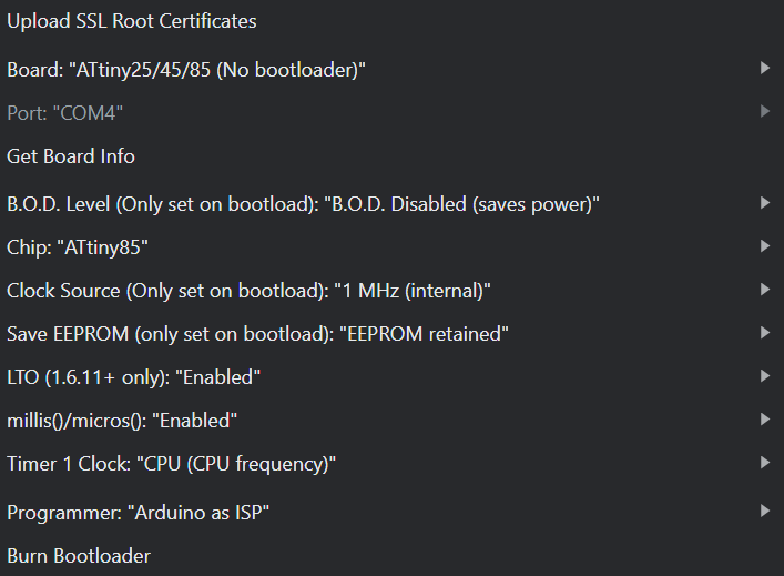
I burned the bootloader before uploading the sketch with the settings shown in the picture above.
You're right, that's weird. It's probably left over from when I was working on setting it up with CTC mode. I changed OCR1A to OCR1C and moved to the Timer1 overflow vector. Unfortunately, no change in behavior. OCR1C must default to 255 and the difference between 25 and 33 milliseconds isn't noticeable to the naked eye.
I do appreciate people spending time trying to help me figure this out. If it's helpful, this is the code and schematic to the emitter end.
#include <avr/io.h>
#include <avr/interrupt.h>
#include "tinysnore.h"

//Initiallize LED_pin variable and set it to digital pin 1 (PB1), which is physical pin 6
const int LED_pin = 1;

void setup() {

  //Set LED_pin to output and a low state
  pinMode(LED_pin, OUTPUT);
  digitalWrite(LED_pin, LOW);

  //Set up timer for 38kHz signal in fast PWM mode
  TCCR1 = 0; // Stop Timer1
  TCNT1 = 0; // Reset Timer1 count
  GTCCR |= (1<<PSR1); // Reset prescaler

  //Turn on fast PWM mode (1<<PWM1A), enable output on OC1A pin (1<<COM1A1),
  //and set prescaler to 1 (1<<CS10). See register description in section 12.3 of ATTiny85 datasheet
  TCCR1  = B01100001;//(1<<PWM1A)|(1<<COM1A1)|(1<<CS10);

  OCR1C = 25; //Set TOP value of counter to 25 to get a 38.4kHz signal. Follow formula on p.87 of datasheet
  OCR1A = 12; //Set approximately 50% duty cycle (half of OCR1C)
}

void loop() {

  TCCR1 |= (1<<COM1A1);//Turn on PWM output
  delayMicroseconds(500);
  TCCR1 &= ~(_BV(COM1A1));//turn off PWM output
  snore(20);//Power down for 20ms
}
Just in case you want a break from timer register manipulation and simply want to get started with integrating the LCD etc., then you can try this (untested but compiles) :
const int IrReceiverPin = 1 ;   // PB1 (physical pin 6 on package)
const int shutter = 4;          // PB4 (physical pin 3 on package)

int num_photo = 4; //will later take input to set during setup
int photo_deltaT = 1000; //will later take input to set during setup

void setup() {

  pinMode( IrReceiverPin, INPUT ) ;
  pinMode(shutter, OUTPUT);

  //test signal to see if setup runs again
  digitalWrite(shutter, HIGH); //sends a signal to the shutter release to take a picture
  delay(5000); //wait 5s
  digitalWrite(shutter, LOW); //turns off signal to shutter release
}

void loop() {
  static uint32_t beamIntactAtMs = millis() ;  // static initialised only once
  uint32_t ms = millis() ;
  if ( digitalRead( IrReceiverPin ) == LOW ) beamIntactAtMs = ms ; // beam intact so update timer
  else if ( ms - beamIntactAtMs > 40 ) {  // beam broken > 40mS
    for (int i = 0; i < num_photo; i++) { //sets a loop to repeat the number of photos taken per trigger
      digitalWrite(shutter, HIGH); //sends a signal to the shutter release to take a picture
      delay(50); //wait 50ms
      digitalWrite(shutter, LOW); //turns off signal to shutter release
      delay(photo_deltaT - 50); //sets the delay time between pictures
    }
    beamIntactAtMs = millis() ; // reset
  }
}
Ha, thanks. This behaves like it's supposed to. I might just end up using that. There's a stubborn part of me that still wants to know why the pin change interrupt didn't work, but I also have limited time to work on this stuff
Thanks. So it is crashing with the pin change interrupt.
Mostly inexperience and curiosity. I worked on the emitter end first, so I had just figured out how to set up a timer. It was neat to look things up in the datasheet and set the individual bits and have them work.
I also had it in my head that I wanted the response to be fast and reliable, so if the code I wrote to check the voltage took too long, it would interrupt that less critical function and keep the critical functions running. Now that I've written the code to check the voltage and timed it, that turned out not to be an issue. By that point I had working code with the external interrupt, and what seemed like working code with the pin change interrupt until there was a delay in the setup. It seemed so close that I didn't want to abandon it.
I did ask Microsoft copilot to generate some code for the emitter, but it was pretty inaccurate, so I ended up rewriting it all. I don't remember asking about the code for the receiver.