I am trying to build a wireless movement sensor using ATTiny85. The circuit works perfectly fine on a breadboard but, when assembled on a general purpose PCB, the PIR sensor gets into a loop! Any interference on the pcb?
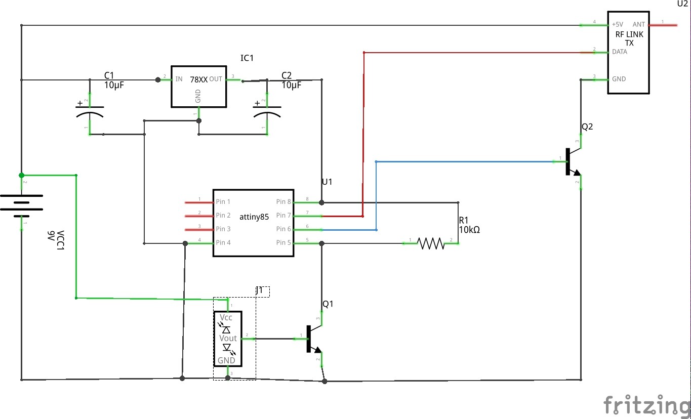
I have attached my schematic and an image of my assembled PCB.
#include <MANCHESTER.h>
#define TxPin 2

unsigned int Tdata = 0;
int TRANSISTOR_PIN = 1;
int PIR_SENSOR_PIN = 0;

void setup()
{
  MANCHESTER.SetTxPin (TxPin);
  pinMode(TRANSISTOR_PIN, OUTPUT);
  pinMode(PIR_SENSOR_PIN, INPUT);
}

void loop()
{
int pirVal=digitalRead(PIR_SENSOR_PIN); //read the state of the motion sensor

if(pirVal == LOW)
  {
    digitalWrite(TRANSISTOR_PIN, HIGH);//transistor ON
    delay(1000);

    Tdata = 50;

    MANCHESTER.Transmit(Tdata); //transmit the signal
    delay(100);

    digitalWrite(TRANSISTOR_PIN, LOW);
  }
  delay(2000);
}
Update: I am unable to upload my pcb image, I get a security check failed message!
It is not a good circuit, you should not switch the RF link by switching the ground, I don't understand the component leading into the base of Q1, what is it?
You seem to have a lack of base resistors on both transistors and you have no decoupling capacitors on the processor, you need at least a 0.1uF ceramic.
Also you seem to be feeding 9V into the 5V pin of the RF link.
I tried a .1uF decoupling capacitor between pin 8 and 4 (vcc and ground) with no luck.
I am switching the RF link to conserve power, I tried switching vcc instead of ground with no change in result. This particular RF link is rated 5v - 12v, I am feeding 9v to get better transmission range, hope that is OK. The component that is leading to the base of Q1 is a PIR sensor with a logic out of 3v when it detects movement.
If I rig the same circuit on a breadboard, it behaves properly. I agree I need base resistors on both Q1 and Q2.
The PCB has a fault (cracked trace or solder/copper whisker joining traces that
should be separate) ?
You burnt out the transistors - coincidently you also moved the circuit to the pcb?
I'd suggest fix known issues and check all components and PCB and test again.
Another possibility (if the difference is repeatable when moving circuit from breadboard
to PCB) is you have oscillations going on. Again fix the issue (add decoupling to each
logic device).
[ Oh yes, a classic one, check with a multimeter than every component is getting
ground and power as appropriate - test from the component leads so all PCB joints
are checked ]
I finally got it working. It was indeed oscillations that was causing the problem. As I don't have an oscilloscope to isolate the source of noise, I used a burte-force approach. I decoupled all the logical components (PIR sensor, tiny, and RF link) with no luck. Then I tried switching the components that were on 9v to 5v. After all the juggling, I figured that I had to move the PIR sensor to 5v and decouple the RF link.